Core Optical Assembly#
Build the basic optical assembly for the DIYraman setup in a backscattering configuration. This module provides the minimum optical path you need to record your first Raman spectra.
The design shown here is built around a surplus B&W Tek spectrometer module, which is commonly available on the used market for around 200€. Other spectrometers with a similar input geometry / SMA905-connector can also be adapted.
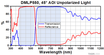
For cost reasons, this setup uses a low-cost 532 nm green laser pointer together with a dichroic mirror (cut-on 550 nm) and a longpass filter (cut-on 550 nm). You can find more information in the respective Parts and Materials sections below or in the BOM. Because the laser operates at 532 nm and the filters begin transmitting at 550 nm, the usable Raman signal will be in the Stokes region above roughly 600 cm⁻¹.
Full vs. Basic Optical Assembly
The Full-Build incorporates the DIY-Linear-Stage along with two stepper motors to motorise the kinematic laser mount for convenience.
The basic setup on this page is intentionally simpler and sufficient to capture your first Raman signals.
Sub-Assemblies#
 |
 |
|---|---|
| Sample Assembly Holds the cuvette and microscope objective on two guide rods. |
Laser Assembly Mounts the excitation laser in a Thorlabs KM100 kinematic mirror mount. |
 |
 |
| Focusing Assembly Filters and focuses the collected signal light towards the fibre / spectrometer input. |
Dichroic Assembly Holds the dichroic mirror that separates laser light from Raman signal. |
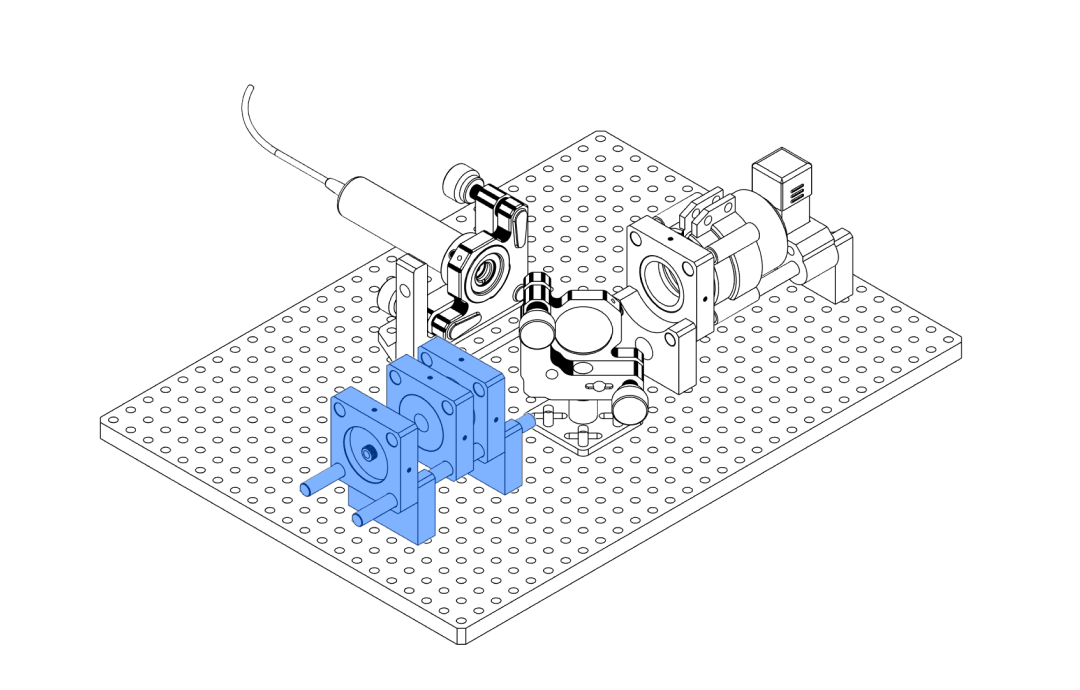
Sample Assembly#
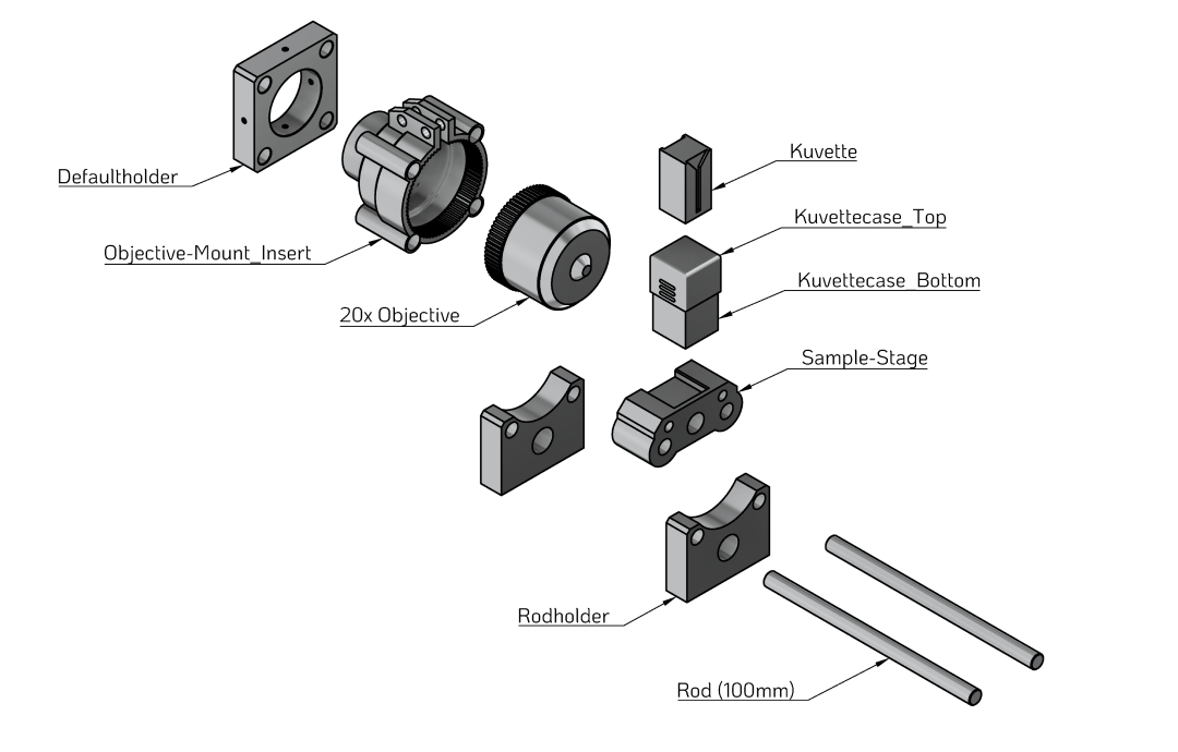
The sample assembly positions the cuvette in front of the microscope objective on a pair of guide rods. Before printing and assembling the parts, make sure that your sourced components (cuvette, rods, objective) match the dimensions of the printed holders.
Parts and Materials#
Visit the complete Bill of Materials
Everything you will need, both printed parts and sourced parts, along with their cost and supplier, can be viewed in the dedicated BOM!
Sourced parts#
| Qty | Name | Model / Spec. | Notes |
|---|---|---|---|
| 1x | Quartz Cuvette | Any | Matching the dimensions of Kuvettecase_Bottom and Kuvettecase_Top. |
| 1x | Microscope objective | Any, Leitz PL Fluotar 20x/0.45 D EPI, oo/0 | Any, 20x, inf.- corrected, WD > Cuvette-Thickness (alternative to printed part: CP42/M) |
| 2x | Guide Rod ⌀ 6 mm, 100 mm | Any, ER Assembly Rods for 30 mm Cage Systems i.e. ER4 (4" ~ 100 mm) | Ideally for optical applications (tight tolerances) |
| 2x | M3 screw + nut |
Printed parts#
| Qty | Part name (.stl) | Print preview |
|---|---|---|
| 1x | Defaultholder |
 |
| 2x | Rodholder |
 |
| 1x | Sample-Stage |
 |
| 1x | Kuvettecase_Top |
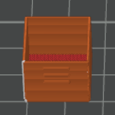 |
| 1x | Kuvettecase_Bottom |
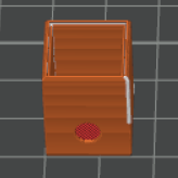 |
| 1x | Objective-Mount_Insert |
 |
Before you print
Make sure your sourced parts are compatible with the printed parts:
- Are the rods the correct diameter for the rod holders?
- Does your cuvette fit into the
Kuvettecase_BottomandKuvettecase_Top? - Does your microscope objective fit into the
Objective-Mount_Insert?
Quick compatibility checklist
- Cuvette →
Kuvettecase_Bottom/Kuvettecase_Top→Sample-Stage - Microscope objective →
Objective-Mount_Insert→Defaultholder - Rods →
Rodholder→Sample-Stage→Objective-Mount_Insert→Defaultholder
Once you have confirmed that your parts match, you can print the components and validate their fit using the steps below.
Step 1 – Check rod fit#
Affected parts
DefaultholderRodholder(2×)Sample-StageObjective-Mount_Insert
To ensure the printed parts slide smoothly but without play on the rods, test-fit a rod through each opening in the parts listed above.
- The rod should pass through with a noticeable but reasonable amount of force. A snug fit minimises wobble and keeps the optical axis stable.
- If the rod does not fit at all, lightly sand the edges of the holes and try again.
- If sanding is not enough, slightly increase the hole compensation (or scale the holes) in your slicer settings and re-print the affected parts.
When sanding printed parts
Fine plastic dust can be harmful if inhaled. Work in a well-ventilated area, wear a dust mask, and wipe the parts with a damp cloth after sanding to remove any remaining dust.
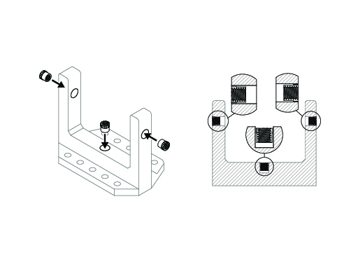
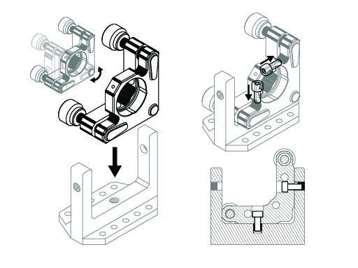
Step 2 – Install the microscope objective#
- Slide the
Objective-Mount_Insertinto theDefaultholderand confirm a smooth, wobble-free fit. - Insert your microscope objective into the
Objective-Mount_Insert. - Insert two M3 screws and two nuts into the clamp mechanism on the side of the mount, as shown in the illustration.
- Make sure the objective sits straight and level in the mount.
- Gently tighten both M3 screws until the objective is held firmly.
- Check from the side that the objective remains aligned parallel to the rods (its optical axis should be parallel to the rod direction).
Do not overtighten
Tightening the screws too much can deform the printed part or the objective barrel. Tighten only until the objective no longer moves if you tap it lightly.
Step 3 – Check the cuvette holder#
- Place your cuvette into the
Kuvettecase_Bottom. Confirm that the contents of the cuvette are visible through the circular opening in the bottom part.
- Slide the
Kuvettecase_Topover theKuvettecase_Bottomwith the cuvette inside. The top should sit tightly and close with some friction. - If the
Kuvettecase_Topis too tight, lightly sand the inside surfaces. Afterwards, wipe off dust with a damp cloth. - If it still does not fit, slightly scale the
Kuvettecase_Topin your slicer (for example, to 101 % in X/Y/Z) and re-print. - The cover is optional but recommended to reduce spills and minimise stray light entering from above.
Step 4 – Assemble the sample sub-assembly#
- Place both
Rodholderparts upright on your workspace and push both rods through the firstRodholder. - Slide the
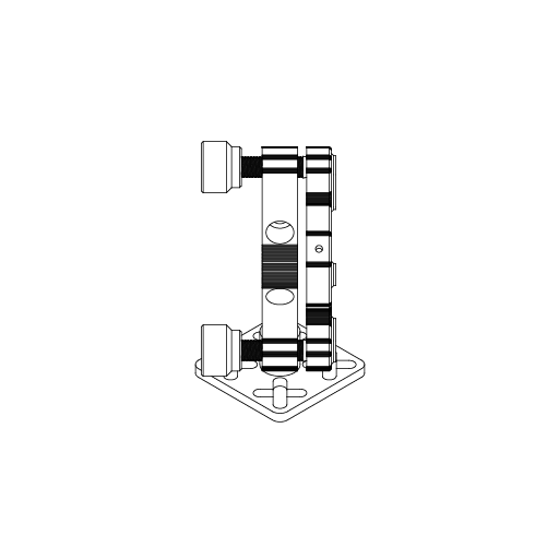
Defaultholder(with mounted objective and insert) and then theSample-Stageonto both rods, as shown in the graphic.
- Push the second
Rodholderonto the rods to lock the parts in place. - Place the
Kuvettecase_Bottomwith the cuvette on theSample-Stageso that the opening faces the microscope objective. It should sit loosely but stably on the stage.
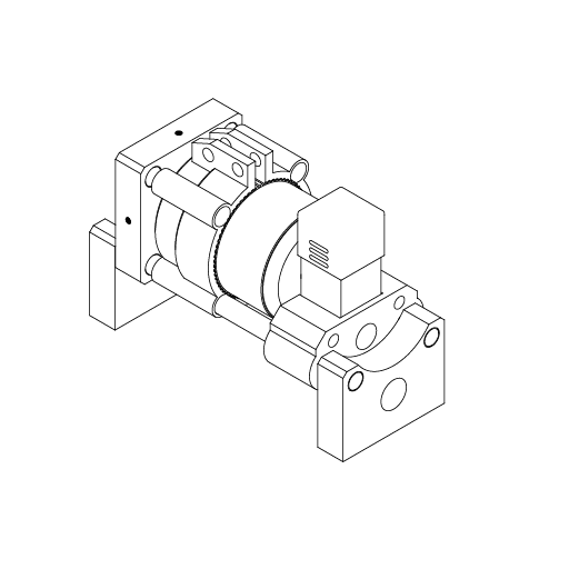
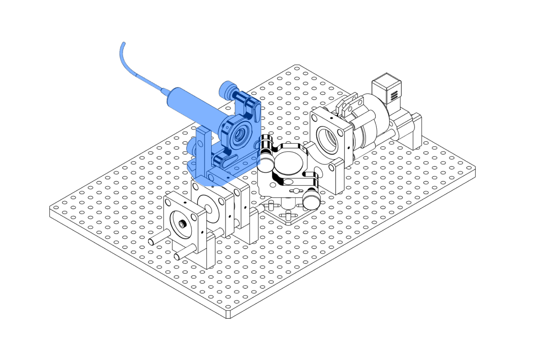
Laser Assembly#
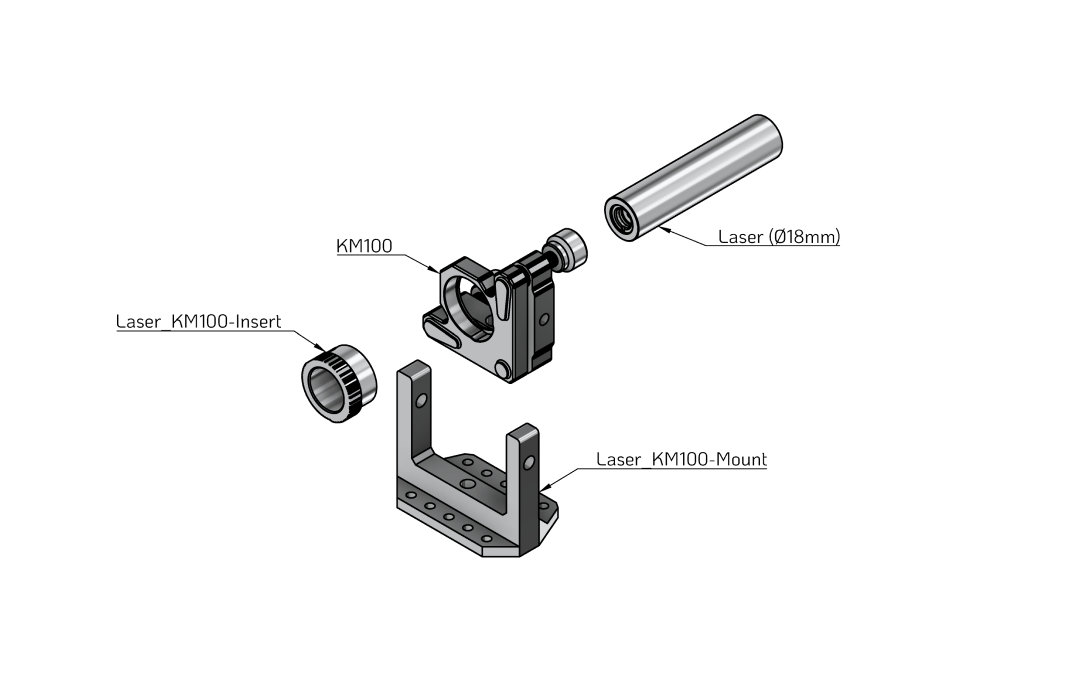
The laser assembly holds a cylindrical laser module in a Thorlabs KM100 kinematic mount using a printed adapter and heat-set threaded inserts.
Parts and Materials#
Visit the complete Bill of Materials
Everything you will need, both printed parts and sourced parts, along with their cost and supplier, can be viewed in the dedicated BOM!
Sourced parts#
| Qty | Name | Model / Spec. | Notes |
|---|---|---|---|
| 1x | Laser 532nm | Any, 532 nm DPSS, 30mW - 70mW, (⌀ 18 mm) | Cylindrical laser module, 18 mm body. |
| 1x | Kinematic Mount | Thorlabs KM100 | Kinematic mirror mount. |
| 2-3x | M4 heat-set insert | ||
| 1x | M3 heat-set insert |
Printed parts#
| Qty | Part name (.stl) | Print preview |
|---|---|---|
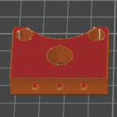
| 1x | Laser_KM100-Insert |
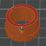 |
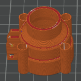
| 1x | Laser_KM100-Mount |
 |
Before you print
Check that the laser body diameter matches the Laser_KM100-Insert.
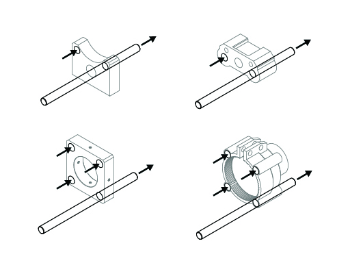
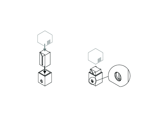
Step 1 – Prepare the printed KM100 mount (heat-set inserts)#
- Insert an M4 brass heat-set insert (slim side first) into the centre opening on the bottom of the
Laser_KM100-Mount. - Using a hot soldering iron with a flat tip, gently press on the insert until the surrounding plastic softens and the insert sinks into the part.
- Stop when the insert is slightly below the plastic surface. The KM100 will sit on this face, so it should remain flat.
- Repeat the process for the side holes in the mount where additional M4 inserts are required (see illustration).
- Allow the part to cool completely before mounting any hardware.
Tools for heat-set inserts
A temperature-controlled soldering iron with a flat tip works well. Dedicated heat-set insert tips are inexpensive and make this step easier.
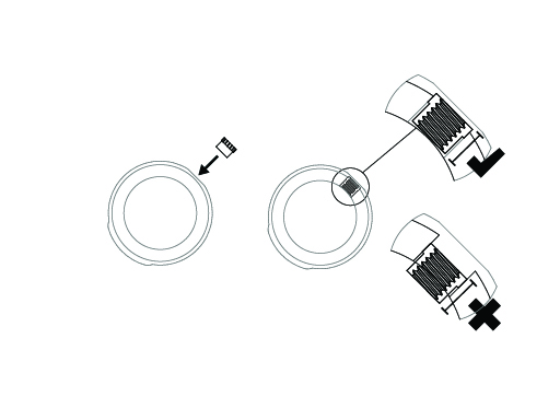
Step 2 – Prepare the laser insert (Laser_KM100-Insert)#
- Heat-set the M3 insert into the small side hole of the
Laser_KM100-Insert. - Make sure the insert does not protrude into the inner bore where the laser will sit. A slight protrusion on the outside is fine.
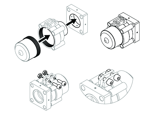
Step 3 – Mount the KM100 in the printed base#
- Place the KM100 on top of the
Laser_KM100-Mountso that the central hole in the KM100 aligns with the centre M4 insert. - The rotation of the KM100 is not critical at this point; the printed mount supports multiple orientations.
- Use one of the supplied M4 screws to fasten the KM100 to the mount. Tighten only until the mount no longer moves freely.
- Use a second screw in one of the side slots if desired to further stabilise the mount.
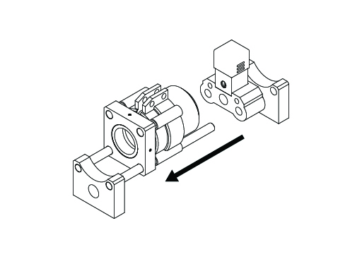
Step 4 – Insert the printed laser adapter#
- Check that the small nylon set screw on the KM100 (perpendicular to the front opening) is loosened so that it does not block the aperture.
- From the front of the KM100, push the
Laser_KM100-Insertinto the circular opening. It should seat firmly but without excessive force. - Apply light pressure with both thumbs until the front face of the printed insert is flush with the inner reference ring of the KM100.
- Lightly tighten the nylon set screw on the KM100 to hold the printed insert in place.
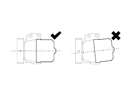
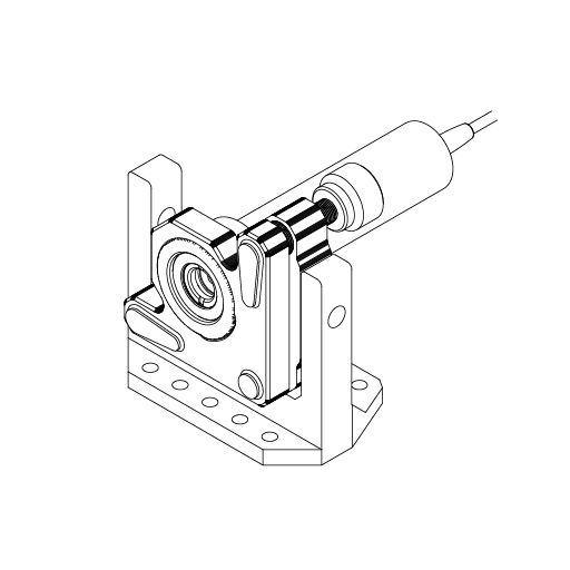
Step 5 – Insert the laser module#
- From the back of the mount, slide the laser module into the
Laser_KM100-Insertthat is now fixed inside the KM100.
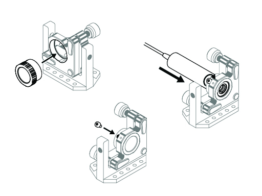
- The exact insertion depth is not critical. Ideally, the laser front face is close to flush with the front of the
Laser_KM100-Insert. - Insert an M3 screw into the M3 heat-set insert in the side of the
Laser_KM100-Insertand gently tighten it until the laser is held securely.
Avoid crushing the laser body
Do not overtighten the M3 clamping screw. Tighten only until the laser can no longer rotate or slide when you try to move it by hand.
Focusing Assembly#
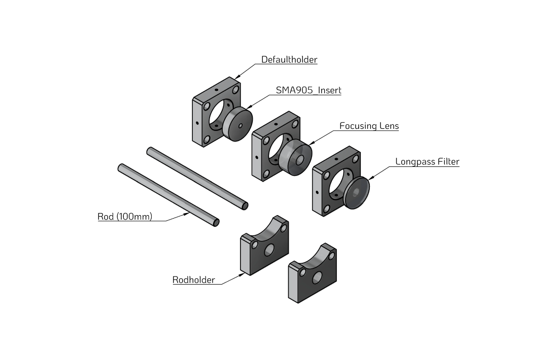
The focusing assembly combines the longpass filter, focusing lens and (optionally) an SMA905 fibre adapter on a pair of rods. This module filters and focuses the Raman signal into the spectrometer input.
Parts and Materials#
Visit the complete Bill of Materials
Everything you will need, both printed parts and sourced parts, along with their cost and supplier, can be viewed in the dedicated BOM!
Sourced parts#
| Qty | Name | Model / Spec. | Notes |
|---|---|---|---|
| 1x | Longpass filter (550 nm) | Thorlabs FELH0550 | |
| 1x | Focusing lens | Thorlabs AC127-019-A - f = 19 mm, Ø1/2" Achromatic Doublet | (mounted in CP32/M) |
| 2x | Guide Rod ⌀ 6 mm, 100 mm | Any, ER Assembly Rods for 30 mm Cage Systems i.e. ER4 (4" ~ 100 mm) | Ideally for optical applications (tight tolerances) |
| 6x | M3 heat-set insert | ||
| 6x | M3 screws |
Printed parts#
| Qty | Part name (.stl) | Print preview |
|---|---|---|
| 3x | Defaultholder |
|
| 2x | Rodholder |
|
| 1x | SMA905_Insert |
 |
Before you print
Confirm that the longpass filter and focusing lens diameters match the openings in the printed Defaultholder parts.
Step 1 – Check rod fit (again)#
The rod fit procedure is identical to Step 1 – Check rod fit in the sample assembly:
- Test-fit the rods through all
Rodholderparts and through the bores in eachDefaultholderthat will sit on the rods. - Adjust with light sanding or slicer hole compensation if necessary.
Step 2 – Prepare the holders (heat-set inserts)#
- Identify the clamping points in the
Defaultholderparts where screws will press on the longpass filter, focusing lens and SMA905 insert. - Heat-set M3 inserts in all corresponding holes so that the inserts sit slightly below the plastic surface.
- Let the parts cool fully before inserting any optics.
Handle optics only after plastic has cooled
Hot plastic can warp or damage optical coatings. Always complete all heating/soldering steps before inserting filters or lenses.
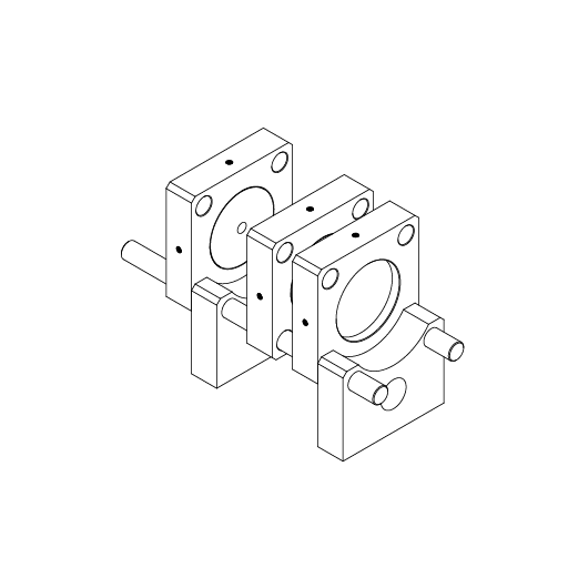
Step 3 – Assemble the focusing module#
- Insert both rods into the first
Rodholder. - Slide the three
Defaultholderblocks onto the rods in the following order (from the sample side towards the spectrometer side): Defaultholderwith theSMA905_Insertand connected SMA905 fibre (if used).Defaultholderholding the focusing lens.Defaultholderholding the longpass filter.- Push the rods through the second
Rodholderto lock the sequence of holders in place.
Orientation of optics
Make sure you keep track of which side of the longpass filter and focusing lens should face the incoming light, according to their datasheets. If in doubt, mark the correct side with a small sticker on the edge before mounting.
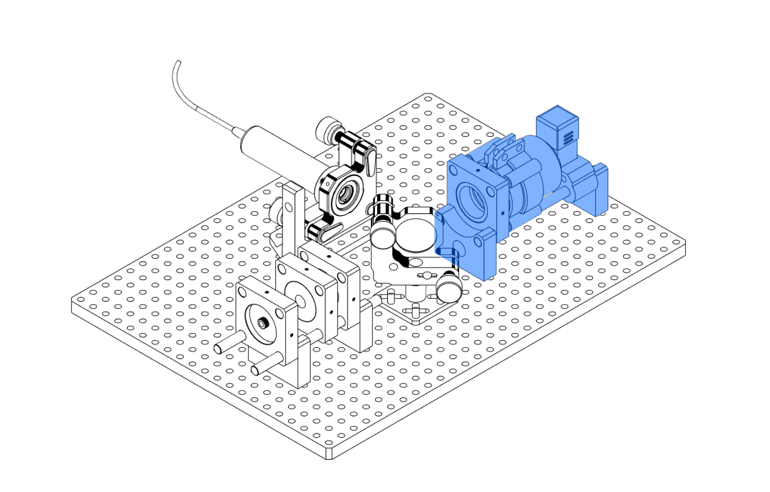
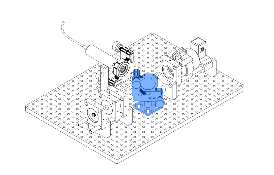
Dichroic Assembly#
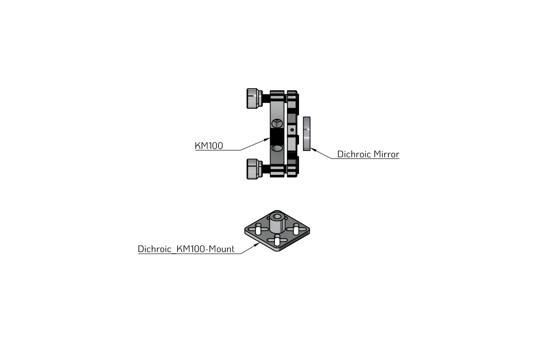
The dichroic assembly mounts a Thorlabs dichroic mirror in a KM100 kinematic mount, held by a printed base that will later sit on the main baseplate. The dichroic separates the excitation laser from the Raman signal.
Parts and Materials#
Visit the complete Bill of Materials
Everything you will need, both printed parts and sourced parts, along with their cost and supplier, can be viewed in the dedicated BOM!
Sourced parts#
| Qty | Name | Model / Spec. | Notes |
|---|---|---|---|
| 1x | Kinematic Mount | Thorlabs KM100 | Kinematic mirror mount. |
| 1x | Dichroic mirror (550 nm) | Thorlabs DMLP550 | |
| 1x | M4 heat-set insert |
Printed parts#
| Qty | Part name (.stl) | Print preview |
|---|---|---|
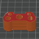
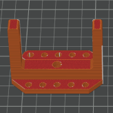
| 1x | Dichroic_KM100-Mount |
 |
Step 1 – Prepare the printed KM100 mount#
- Insert the M4 heat-set insert into the central hole of the
Dichroic_KM100-Mount. - Using a hot soldering iron, press the insert straight into the opening until it sits slightly below the plastic surface.
- Position the KM100 on the
Dichroic_KM100-Mountso that the bottom screw hole aligns with the M4 insert. - Use one of the provided M4 screws to fasten the KM100 to the mount until it no longer moves freely, but can still be rotated with gentle force.
Rotation during alignment
Later, on the baseplate, the KM100 will be rotated to 45° with respect to the incoming laser beam. You will slightly loosen this screw again to set that angle.
Step 2 – Install the dichroic mirror#
Handle optics carefully
Work in a clean area and wear powder-free nitrile gloves. Avoid touching the coated surfaces and never wipe them with dry cloths.
Source: Thorlabs – “Longpass Dichroic Mirrors/Beamsplitters”
- Review the Thorlabs handling guide for high-performance optics:
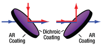
Thorlabs – Optics Handling and Care. - The dichroic mirror is directional: one side carries the dichroic coating (reflecting the laser, transmitting the Raman signal), the other side carries an anti-reflection (AR) coating.
Source: Thorlabs – “Longpass Dichroic Mirrors/Beamsplitters”
- On the Thorlabs DMLP550, the dichroic side is indicated by a small engraved arrow pointing towards the coated surface. This arrow is etched on the outer edge and can be hard to see in dim light.
- With clean powder-free nitrile gloves, carefully hold the dichroic by its outer edge and locate the engraved arrow.
- Insert the dichroic mirror into the KM100 so that:
- The dichroic (arrow-marked) side faces the incoming laser beam (front side).
- The AR-coated side faces towards the KM100 adjustment knobs (back side).
- Gently tighten the nylon set screw on the KM100 until the dichroic sits evenly and flush in the mount.
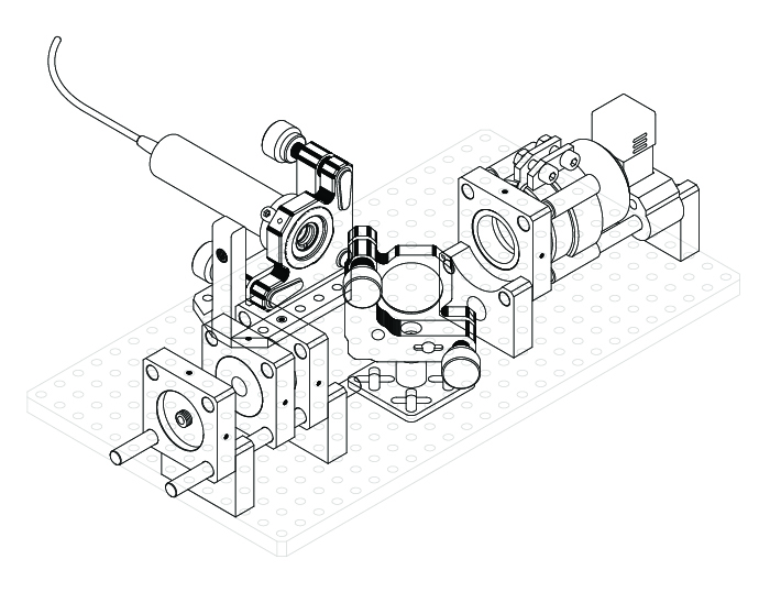
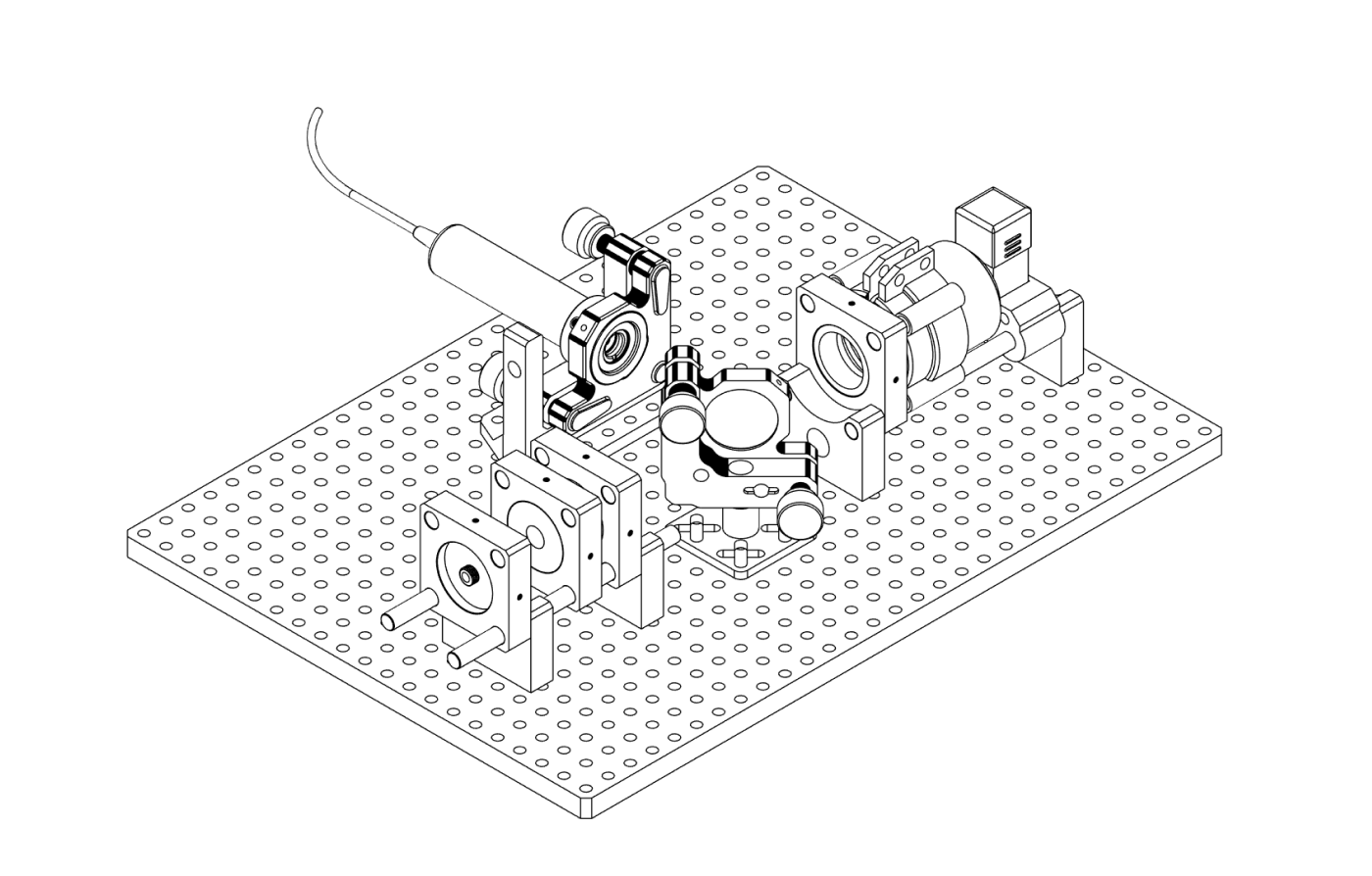
Baseplate Mounting#
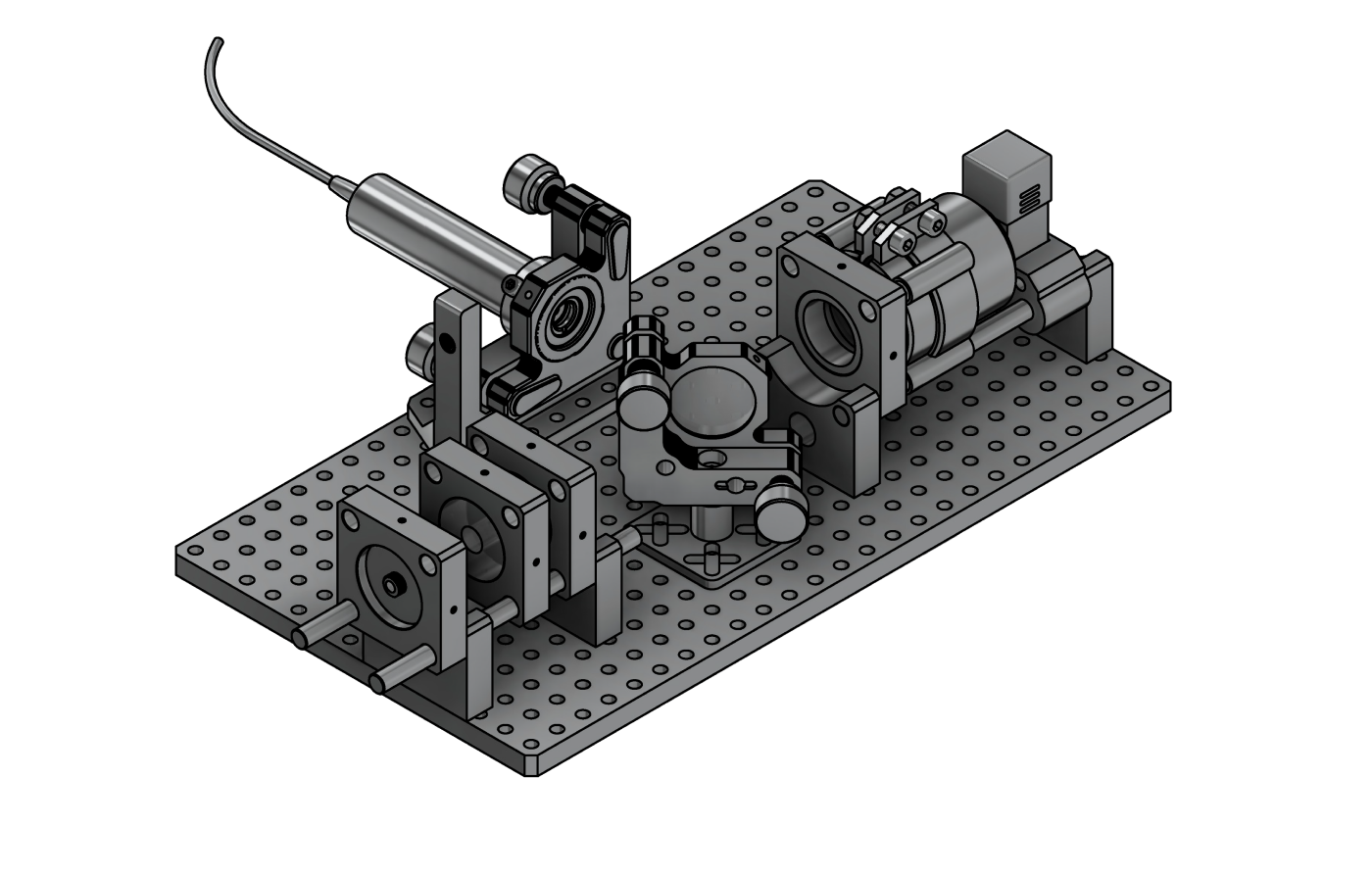
In this final step you mount all sub-assemblies onto the baseplate to form the complete basic Raman optical assembly.
Parts and Materials#
Visit the complete Bill of Materials
Everything you will need, both printed parts and sourced parts, along with their cost and supplier, can be viewed in the dedicated BOM!
Sourced parts#
| Qty | Name | Notes |
|---|---|---|
| 1x | Sample Assembly | |
| 1x | Laser Assembly | |
| 1x | Focusing Assembly | |
| 1x | Dichroic Assembly | |
| 14x | M4 screw, 16 mm | For fastening sub-assemblies to the baseplate. |
| 6x | M4 nut | For additional clamping where required. |
Printed parts#
| Qty | Part name (.stl) | Print preview | Notes |
|---|---|---|---|
| 1x | Baseplate_Small |
 |
250 × 140 × 7 mm |
Step 1 – Mount the sub-assemblies onto the baseplate#
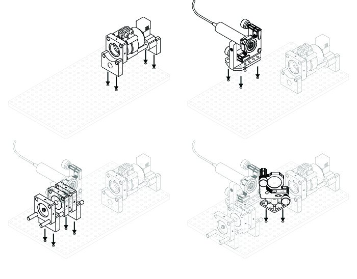
- Mount the Sample Assembly using four M4 screws from the bottom of the baseplate.
- Mount the Laser Assembly using four M4 screws from the bottom and four M4 nuts from above to tighten.
- Mount the Focusing Assembly using four M4 screws from the bottom.
- Mount the Dichroic Assembly using two (or four) M4 screws from the bottom and the corresponding M4 nuts from above.
Fine-tune the dichroic assembly
The dichroic assembly as a whole is designed to move in X/Y direction to allow for positional adjustments. You may want to re-position the assembly within the bounds of its mount later on, so do not overtighten screws and nuts at this stage.