DIY Linear Stage#
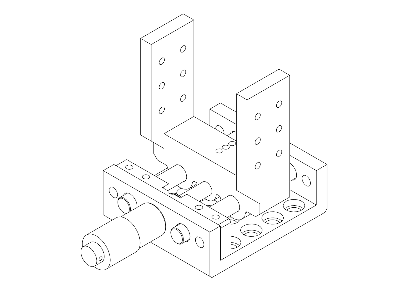
Build a compact linear translation stage for fine axial adjustment of the focusing optics in the Full-Build.
This stage uses:
- Two smooth metal rods as linear guides
- A micrometer screw for precise movement
- Two compression springs to pre-load the moving stage
The design is simple to print and tune, and accurate enough to focus the final lens or fibre position onto the spectrometer input.
Where this stage is used
In the recommended build path, this translation stage sits underneath the Focusing Assembly Focusing Assembly in the Full-Build.
It is not required for the Core-Assembly but strongly recommended for comfortable fine focus adjustment.
Parts and Materials#
![]()
Visit the complete Bill of Materials
Everything you will need, both printed parts and sourced parts, along with their cost and supplier, can be viewed in the dedicated BOM!
Sourced parts#
| Qty | Name | Model / Spec | Notes |
|---|---|---|---|
| 1x | Micrometer screw | ~10-15 mm travel | With mounting nut/collar |
| 2x | Guide Rod ⌀ 6 mm, 55 mm | Any, ER Assembly Rods for 30 mm Cage Systems | Ideally for optical applications (tight tolerances) |
| 2x | Compression spring | ⌀ ≥ 6 mm | Stiffness chosen for light pre-load |
| 4x | M3.5 screw + washer + nut | ~12 mm length |
Printed parts#
| Qty | Part name (.stl) | Print preview |
|---|---|---|
| 1x | LinearStage_Base |
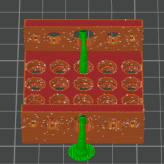 |
| 1x | LinearStage_Stage |
 |
| 1x | LinearStage_Frontplate |
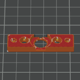 |
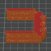
| 1x | LinearStage_L-Bracket |
 |
Preparing the Printed Parts#
Good rod fit is critical for smooth and repeatable motion. Before full assembly, verify and tune the fit of the rods in both the base and the moving stage.
Step 1 – Base#
For the base, the rods should press in firmly and not move once installed.
- Measure the rod diameter with digital callipers to confirm ~⌀ 6.0 mm.
- Push each rod all the way through the rod holes in
LinearStage_Base:
- You should feel noticeable, even resistance as the rod enters the holes.
-
Once inserted, the rods should not wobble or rattle in the base.
-
If the rods do not fit at all:
- Lightly sand the inside of the rod holes with rolled-up sandpaper.
- Clean the dust and test the fit again. Repeat until the rod can be pressed through with firm pressure.
Sanding fibre-reinforced filaments
When sanding PETG-CF or similar materials, wear appropriate PPE (at least a particle mask). Fine fibres and plastic dust can be harmful if inhaled, especially with repeated exposure.
- If the rods have visible play:
- First confirm that the rods are actually ⌀ 6.0 mm (cheap rods can vary).
- If rods are correct, consider slightly shrinking the holes in your CAD/source file or using slicer hole compensation to reduce the effective hole size, then re-print the base.
Print seam settings
If your slicer allows it, use random seam positioning for this part. This avoids a single pronounced seam ridge inside the hole that can interfere with accurate rod fit.
Step 2 – Stage#
The stage must slide smoothly on the rods with minimal play.
- Insert a rod into one of the holes in
LinearStage_Stageand push it through:
- The rod should move with slight resistance but not bind or jam.
-
A small amount of stiffness is acceptable and often improves after some movement or light lubrication.
-
Repeat for the second rod hole. Both rods should slide similarly.
-
If the fit is too tight or jerky:
- Very lightly sand the inside of the rod holes.
-
Clean the dust and test again.
-
If the fit is very loose and the stage can tilt on the rods, consider:
- Reducing the hole size in the source file or with slicer hole compensation, then re-printing, or
Clean after sanding
After sanding, remove dust with compressed air or a vacuum and wipe the parts with a damp paper towel. Loose particles can increase friction and wear over time.
Assembly#
Once the printed parts are tuned for proper rod fit, you can assemble the stage.
Step 3 – Install the micrometer screw#
- Insert the micrometer head into the central opening of
LinearStage_Basefrom the front. - Use the nut supplied with the micrometer to secure it against the base.
- Make sure that:
- The micrometer axis is aligned with the central recess in the
LinearStage_Stage. - The micrometer body does not collide with the rods or springs over the full range of motion.
Avoid overtightening the micrometer nut
Tighten only until the micrometer body does not move when you try to rotate or pull it by hand. Over-tightening can warp the printed base or damage the micrometer threads.
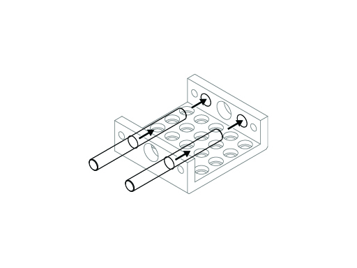
Step 4 – Install rods and stage#

- Insert both ⌀ 6 mm rods from the same side of the
LinearStage_Base. Push them approximately one third of the way in. - Position the
LinearStage_Stageso that its central recess faces the tip of the micrometer screw. - Carefully align the two rod holes in the stage with the rods and slide the stage onto the rods.
- Make sure the micrometer tip sits in the central recess of the stage or contacts the intended push surface.
- Push the rods further through the base and stage until they protrude slightly on the opposite side, leaving room for the springs.
Do not force misaligned rods
If the rods do not slide through the stage easily, remove the stage and check alignment. Forcing misaligned rods can crack the printed part or bend the rods.
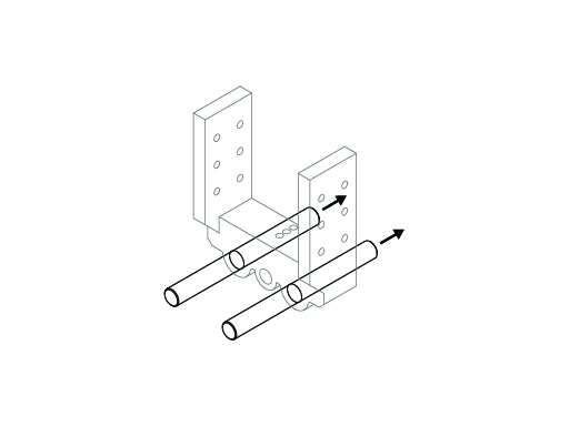
Step 5 – Add the springs#
- Slide one compression spring onto each rod.
- It is often easiest to place the spring on the rod first and then compress it into the recess between base and stage.
- Seat each spring so it sits between the base and the stage in the intended recess, providing a light pushing force against the stage.
- Push the rods fully into the base until:
- The springs are slightly pre-loaded (compressed a few millimetres), and
- The rods are fully seated in both ends of the base.
- Gently turn the micrometer screw to move the stage through its travel:
- The stage should move smoothly with no sudden jumps.
- There should be minimal backlash (lost motion) when reversing direction.
- The springs should stay seated and not buckle.
- Apply a small amount of lubricant to the rods if needed to improve the feel of the motion.
Step 6 – Optional: Frontplate#
- Align
LinearStage_Frontplatewith the corresponding holes on the front of theLinearStage_Base. - Fix the front plate with four suitable screws (e.g. M3.5 with washers and nuts), tightening evenly.
- Verify that:
- The rods remain parallel and properly seated.
- The stage still moves freely over the desired range.
- The micrometer tip remains correctly engaged with the stage.
The front plate increases stiffness at the front end of the rods and reduces the risk of flex when the stage changes direction.
Mounting to the Raman Baseplate#
In the Full Raman Optical Assembly, this stage is mounted beneath the focusing optics module.
- Identify the mounting pattern for the translation stage on your Raman baseplate (see Full-Build).
- Disassemble the desired
Defaultholderthat holds the focusing lens by sliding it off the assembly rods. - Use four screws to mount the optic holder to the stage.
- Place the assembled linear translation stage on the baseplate and align the mounting holes.
- Use four screws and nuts to fasten the stage - using an L-bracket - to the baseplate.
- Tighten all screws evenly, then verify that the stage still moves smoothly, no screw heads interfere, and that the micrometer remains accessible from the desired side.
Orientation on the baseplate
Mount the stage so that the micrometer is accessible from the front or side you find most convenient when adjusting. The exact orientation is not critical as long as the axis of motion aligns with the optical axis of the focusing optics.
Design Notes and Tuning#
For this design, part of the micrometer’s total travel is intentionally used to:
- Pre-load the springs (so the stage is always pressed firmly against the micrometer tip), and
- Avoid fully compressing the springs at the end of travel (to keep motion smooth and predictable).
In practice, the useful travel of the stage is around 5 mm, which is more than sufficient for fine focus adjustment of the final lens (or fibre input) in the Full-Build.
The spring pre-load:
- Reduces backlash when reversing micrometer direction
- Keeps the stage under constant tension
- Improves repeatability of small position changes
Tuning the feel
You may need to experiment with different springs and pre-load amounts.
- Too little tension → noticeable backlash and vague response when reversing.
- Too much tension → high torque required on the micrometer, especially near travel limits.
Aim for a point where the stage moves smoothly and repeatably with moderate turning force.