Dustproof Workspace#
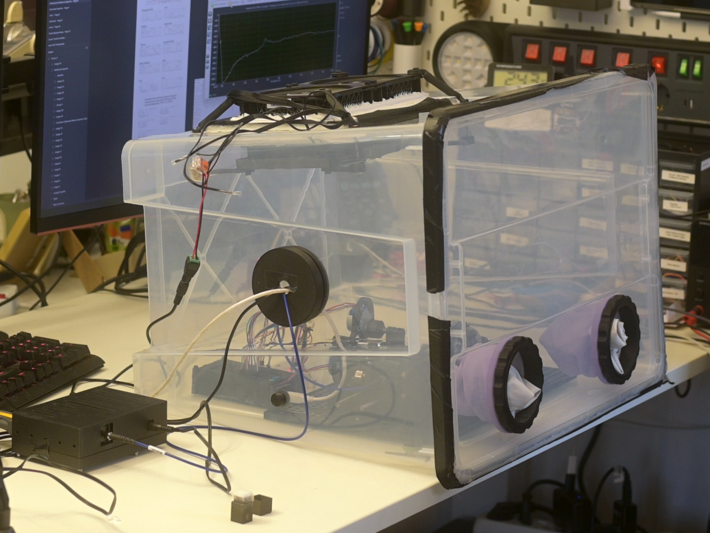
Build a simple overpressure glove box to keep dust and airborne contaminants away from your Raman optics while you mount and align sensitive components such as the dichroic beamsplitter and longpass filter.
In this configuration, two fans push air into the box through a HEPA filter. The slight overpressure forces air out through any small leaks or gaps, so dust-laden air from the room cannot enter the enclosure.
Why overpressure?
- Sealed box: Better than working in open air, but leaks and each opening event can let dust in.
- Underpressure (negative pressure): Used when you must contain hazardous materials - all inlet and outlet paths must be carefully filtered.
- Overpressure (this design): Easier to build for DIY use. Incoming air is filtered once; leaks push clean air out instead of pulling dirty air in.
This glove box is sized around an off‑the‑shelf IKEA SAMLA box but the concept works with any similar transparent container that can take cut‑outs for fans, filter and glove ports.
Parts and Materials#
Visit the complete Bill of Materials
Everything you will need, both printed parts and sourced parts, along with their cost and supplier, can be viewed in the dedicated BOM!
Sourced parts#
| Qty | Name | Model / Spec | Notes |
|---|---|---|---|
| 1x | Storage box | IKEA SAMLA, transparent, 57×39×42 cm |
Any similar box works, separate lid that forms tight seal is ideal. |
| 1x | HEPA filter | IKEA UPPATVIND | Any HEPA / fine dust filter of similar size works. Higher filtration = more pressure drop. |
| 2x | PC fan | Any, 120 mm PC fan | 12V DC fans. Check current draw and airflow rating. |
| 2x | Gloves | Any, long‑sleeved chemical or dishwashing gloves | Choose gloves long enough to reach all areas inside the box. |
| 14x | M4 screw + nut | Hex socket head cap screw | Mixture of lengths below. |
| 4x 4x 2x 4x |
M4 × 12 mm M4 × 16 mm M4 × 20 mm M4 × 65 mm |
Printed parts#
| Qty | Part name (.stl) | Used in | Print preview |
|---|---|---|---|
| 1x | Fan_Connector‑Bracket |
Fan / filter assembly | 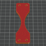 |
| 1x | Fan_Baseplate |
Fan / filter assembly | 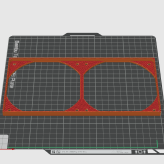 |
| 2x | Filter_Holder‑Clamp |
Fan / filter assembly | 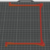 |
| 4x | Fan_Outer‑Bracket |
Fan / filter assembly | 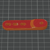 |
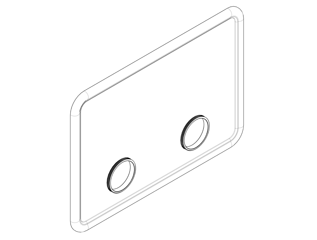
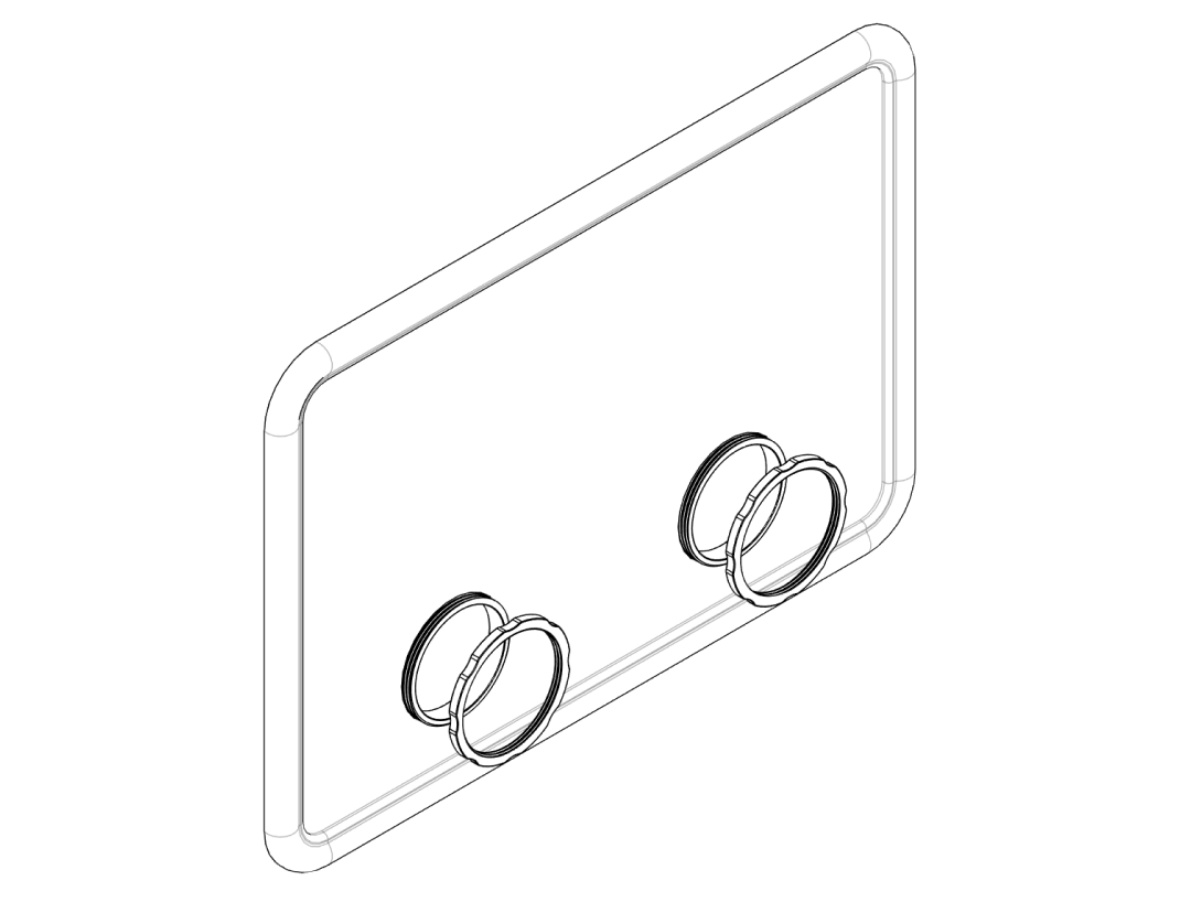
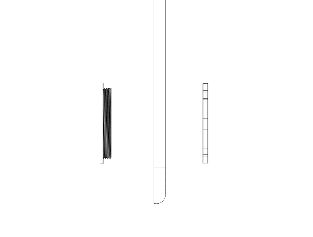
| 2x | Glove‑Insert_Inner |
Glove ports | 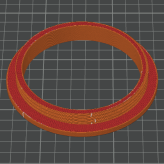 |
| 2x | Glove‑Insert_Outer‑Ring |
Glove ports |  |
| 1x | Large‑Insert_Inner |
Large service port | 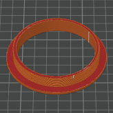 |
| 1x | Large‑Insert_Threaded‑Cover |
Large service port | 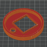 |
| 1x | Large‑Insert_Outer‑Cover‑Open |
Large service port | 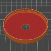 |
| 1x | Large‑Insert_Outer‑Cover‑Closed |
Large service port | 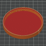 |
| 1x | Cable‑Insert_Inner |
Cable / feedthrough port | 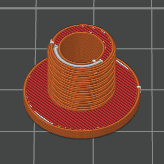 |
| 1x | Cable‑Insert_Nut |
Cable / feedthrough port | 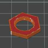 |
| 1x | Cable‑Insert_Cover |
Cable / feedthrough port |  |
Notes for printing#
Suggested print settings
- Material: PETG-CF or ABS recommended for best strength.
- Layer height: 0.2 mm.
- Infill: 30–40 % gyroid or cubic.
- Perimeters: ≥ 3 perimeters (walls) for brackets and inserts.
- Colour: Any - black preferred; opaque colours reduce stray light inside the box.
All parts are designed to print without support on a typical 0.6 mm nozzle - 0.4 is even better but sub-optimal for abrasive PETG-CF. For parts that clamp the box wall (fan brackets and glove inserts), ensure accuracy of holes and circular cutouts. If your printer tends to undersize holes, you can slightly scale the part in X/Y or adjust hole compensation in your slicer.
Instructions#
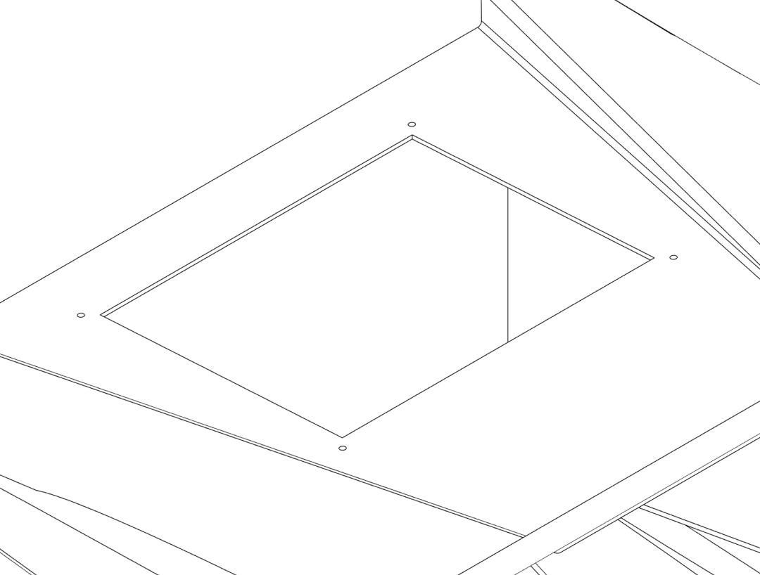
1. Preparing the box#
In this section you mark and cut all openings in the box and lid: the fan / filter opening, glove ports, cable feedthrough and large service port.
Step 1.1 – Marking the cutouts#
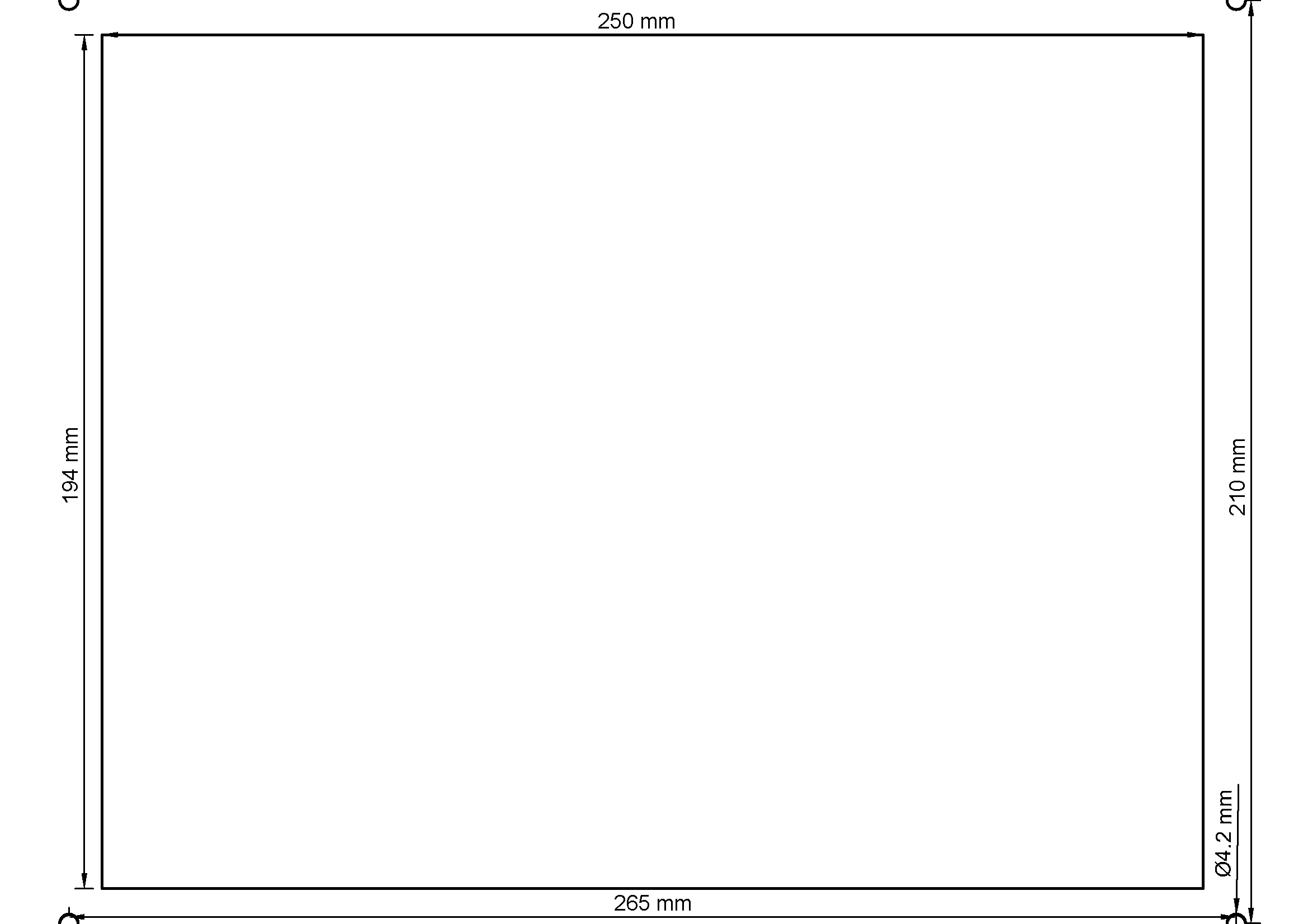
Printable template
An A4 PDF template is provided in the repository. Print at 100 % scale (no scaling) and check at least one dimension with a ruler before cutting.
- Clean the outer surfaces of the box and lid so masking tape will adhere.
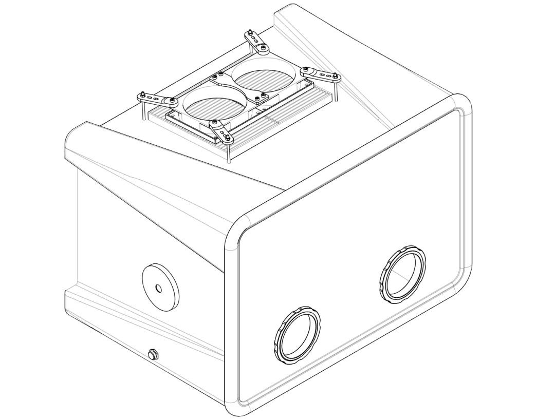
- On the top of the box, tape the printed template in place and align it with the centre of the lid as shown in the PDF / images.
- Mark the following on the box with a non‑permanent marker:
- Main fan/filter opening: 250 × 195 mm rectangular cutout.
- Fan mounting holes: 4 × holes at the corners for M4 screws (drill 4 mm).
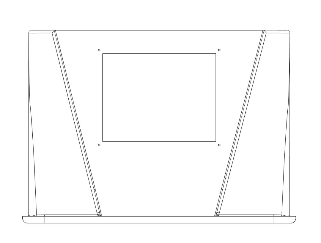
- On the front side of the lid, mark two circular openings for the glove ports:
- Glove inserts: 2 × circles, 96 mm diameter each.
- On the left side of the box, mark:
- Large insert: 1 × circle, 72 mm diameter.
- Cable insert: 1 × hole, 12 mm diameter.
Check dimensions twice
Before cutting, verify all positions and diameters with the corresponding 3D‑printed inserts. The parts should cover a few millimetres of plastic around each cutout for a good seal.
Step 1.2 – Cutting and drilling#
- Drill a starter hole inside each closed shape (rectangles / circles) using a drill bit sized for your cutting tool (e.g. 6–8 mm).
- For the rectangular top opening, insert a fine‑tooth jigsaw blade or rotary tool and carefully cut along the marked lines.
- For the circular openings, use a hole saw, step bit, or carefully cut along the line with a rotary tool.
- Drill the M4 mounting holes (4 mm diameter) at the marked fan / filter positions.
- Deburr all edges with a file or fine sandpaper so the printed parts sit flush.
Cutting plastic safely
- Wear safety glasses and a dust mask.
- Clamp the box securely so it cannot move while cutting.
- Work slowly to avoid cracking the plastic.
2. Fan assembly#
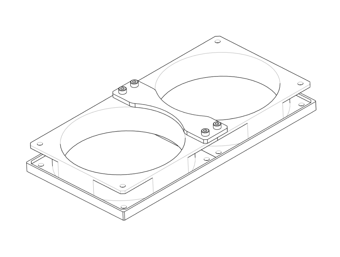
In this step you assemble the fan on its printed baseplate and outer brackets.
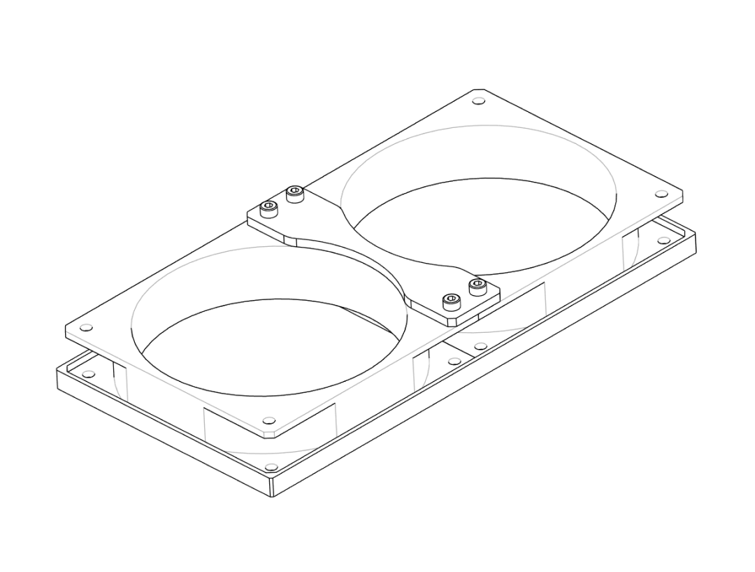
Step 2.1 – Mount the fan to the baseplate#
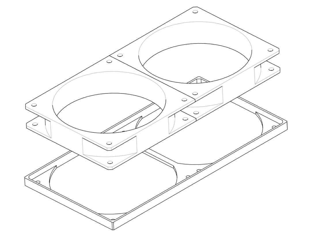
- Place the
Fan_Baseplateon your workspace with the flat side down. - Orient the 120 mm fan so that it will blow air into the box when mounted (the airflow arrow on most fans should point towards the box).
- Align the fan’s mounting holes with those in the
Fan_Baseplate. - Use four suitable screws (e.g. M4 × 12 mm) to fasten the fan to the baseplate.
Fan orientation
If your fan has a label and struts on one side: usually the strut side is the air outlet. For this design, the outlet should face towards the box.
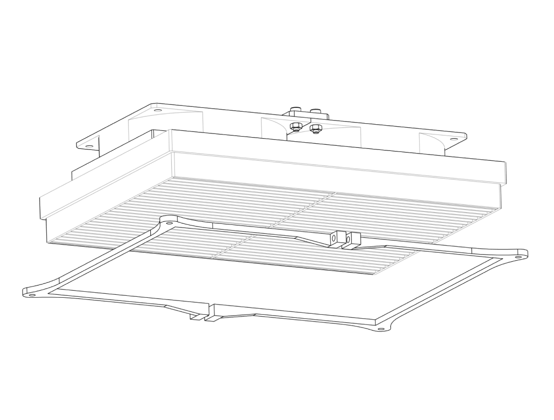
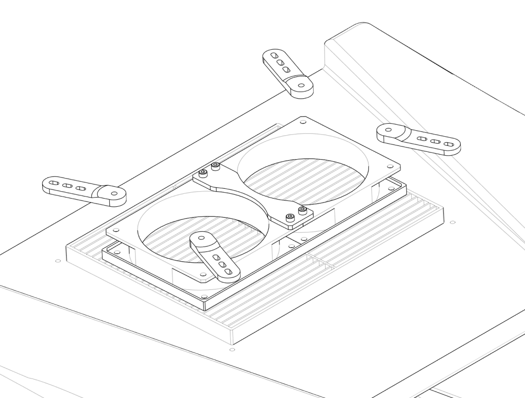
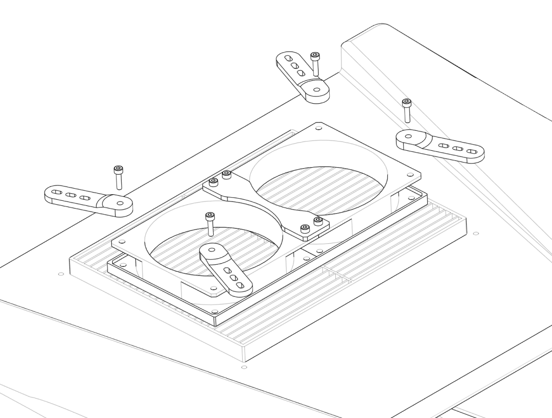
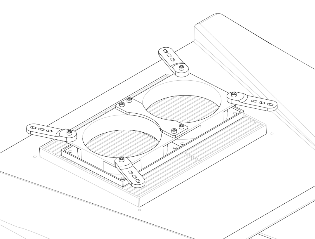
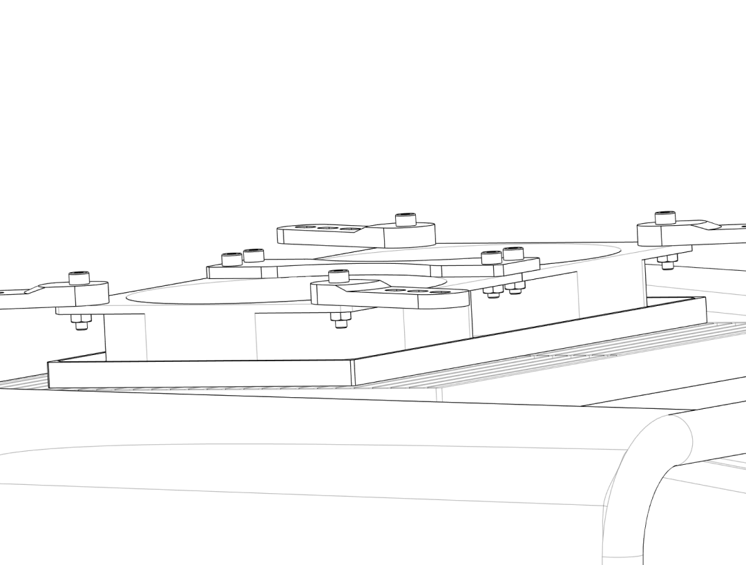
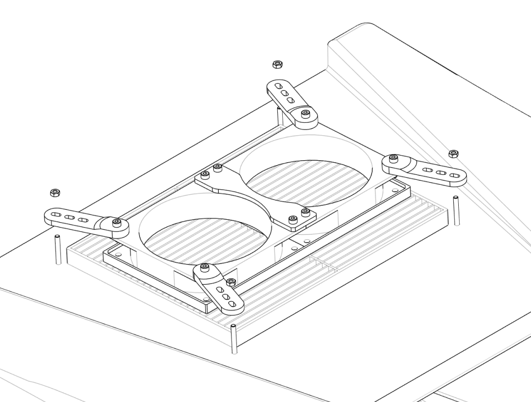
Step 2.2 – Attach outer brackets#
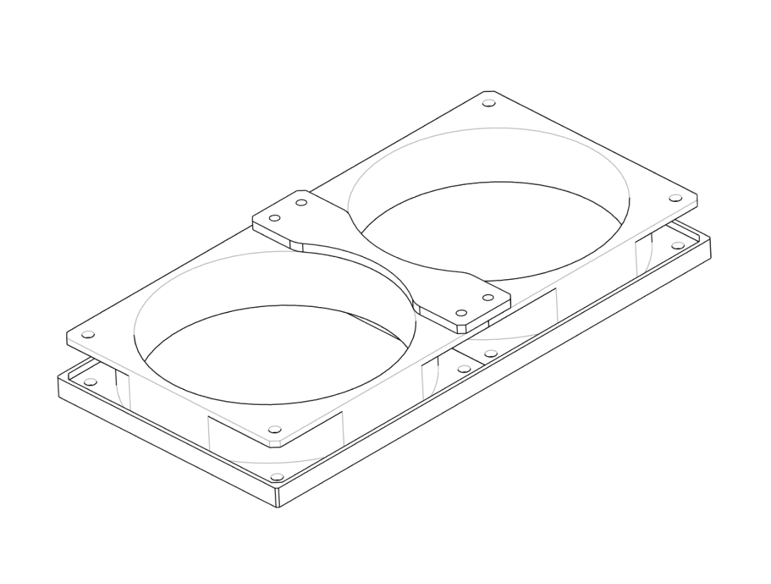
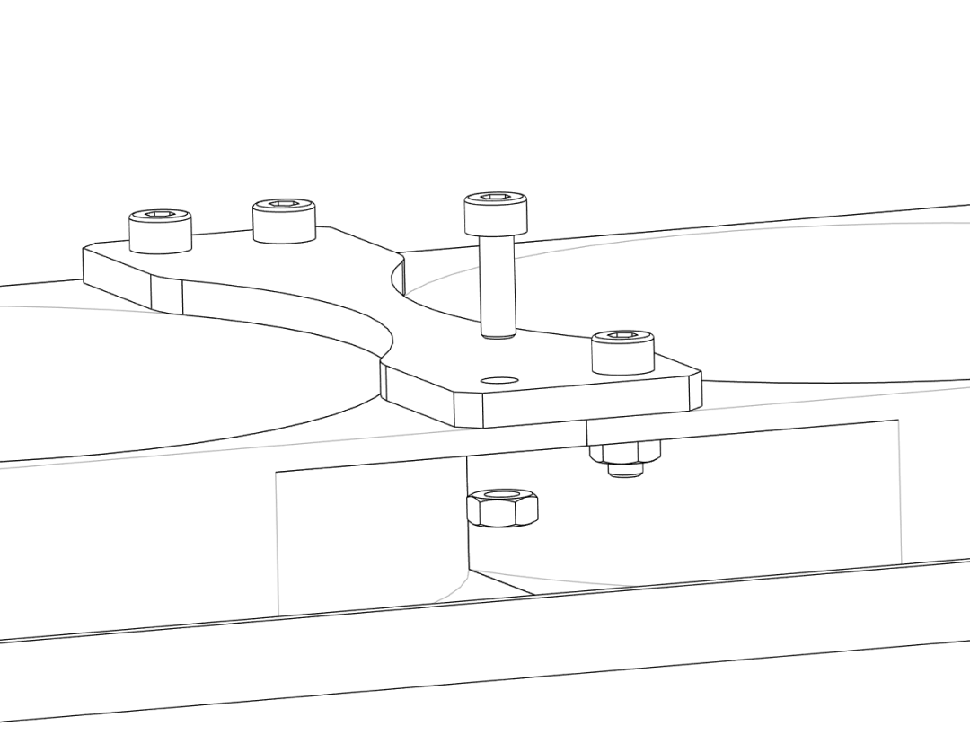
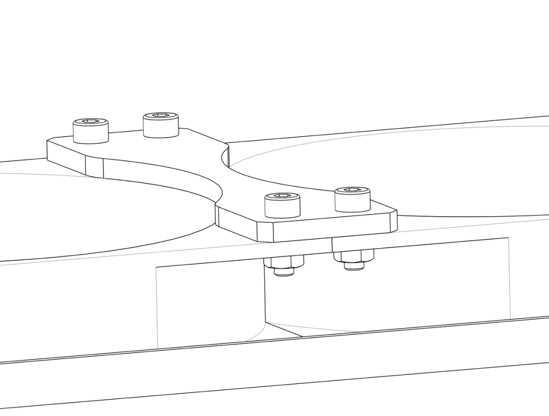
- Attach the
Fan_Connector‑BracketandFan_Outer‑Brackets to theFan_Baseplateaccording to the exploded view in the project files. - Use M4 screws and nuts where provided to secure the brackets.
- Double‑check that all parts sit flat and that nothing interferes with the fan blades.
3. Mounting fan and filter on the box#
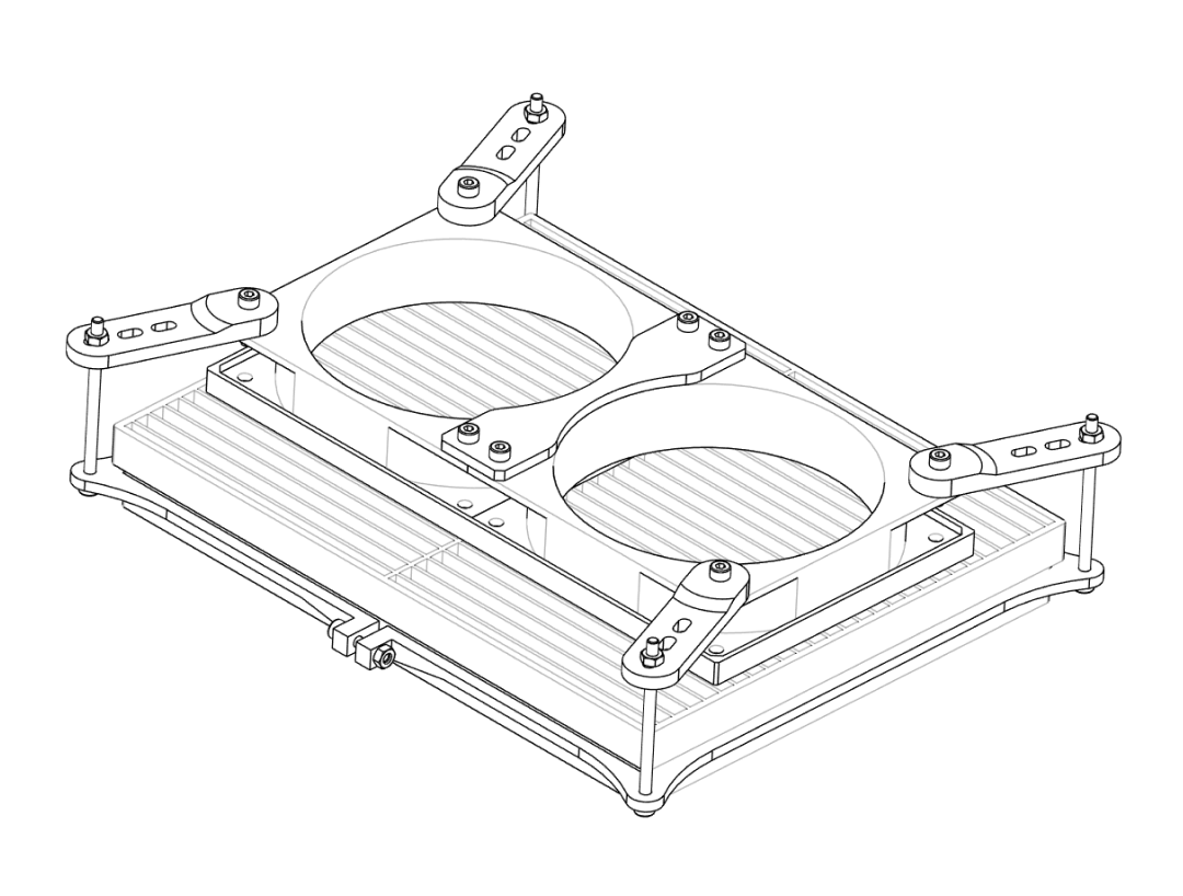
In this step you clamp the HEPA filter and the fan assembly to the top of the box.
Step 3.1 – Position the HEPA filter#
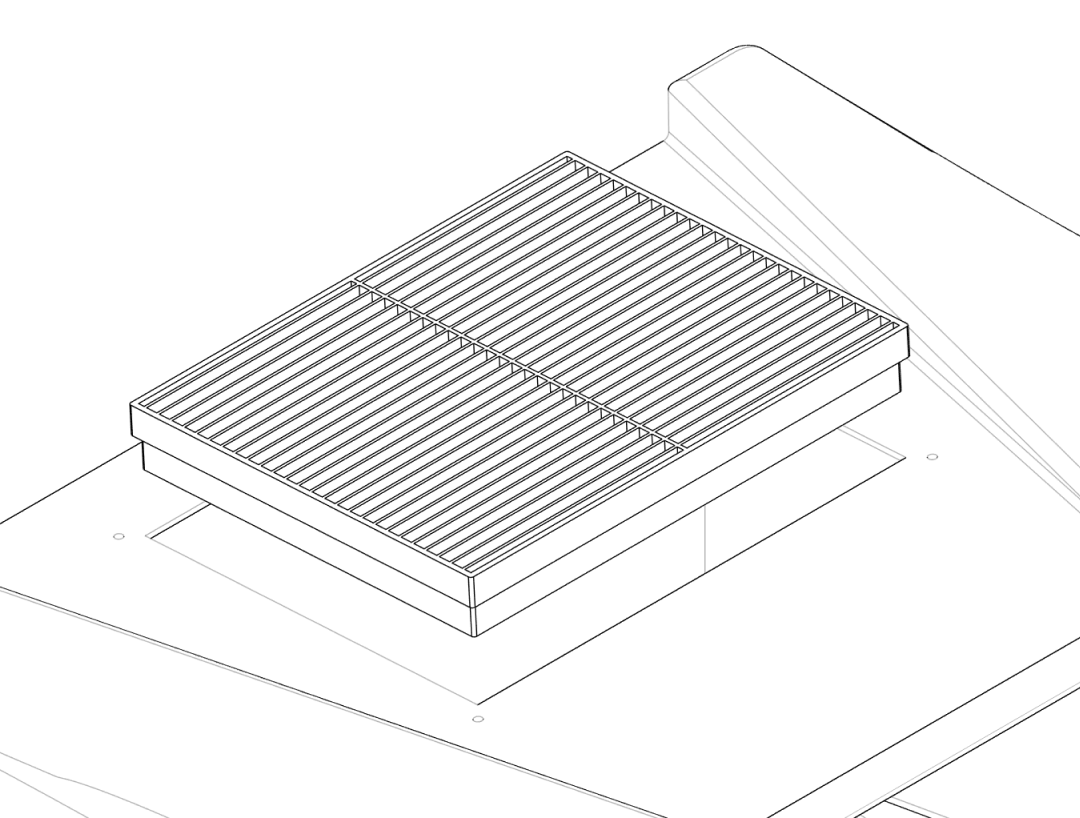
- Place the box so that the top opening faces upwards.
- Lay the HEPA filter on the inside of the lid or box top so it completely covers the 250 × 195 mm rectangular cutout.
- Align the edges so that the filter frame sits evenly and there is enough overlap for a good seal.
- The filter should stay in place on its own, sitting on the outer lip.
- Position the
Filter_Holder‑Clampparts on the inside, over the filter frame, aligned with the drilled M4 holes.
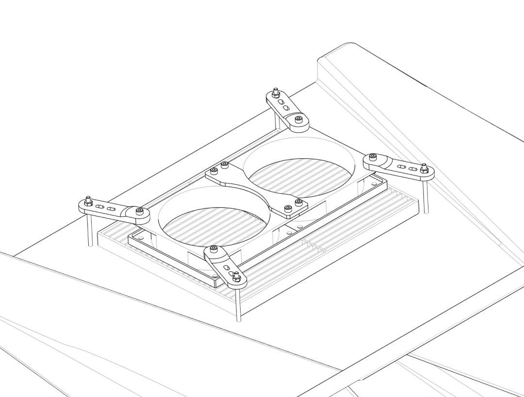
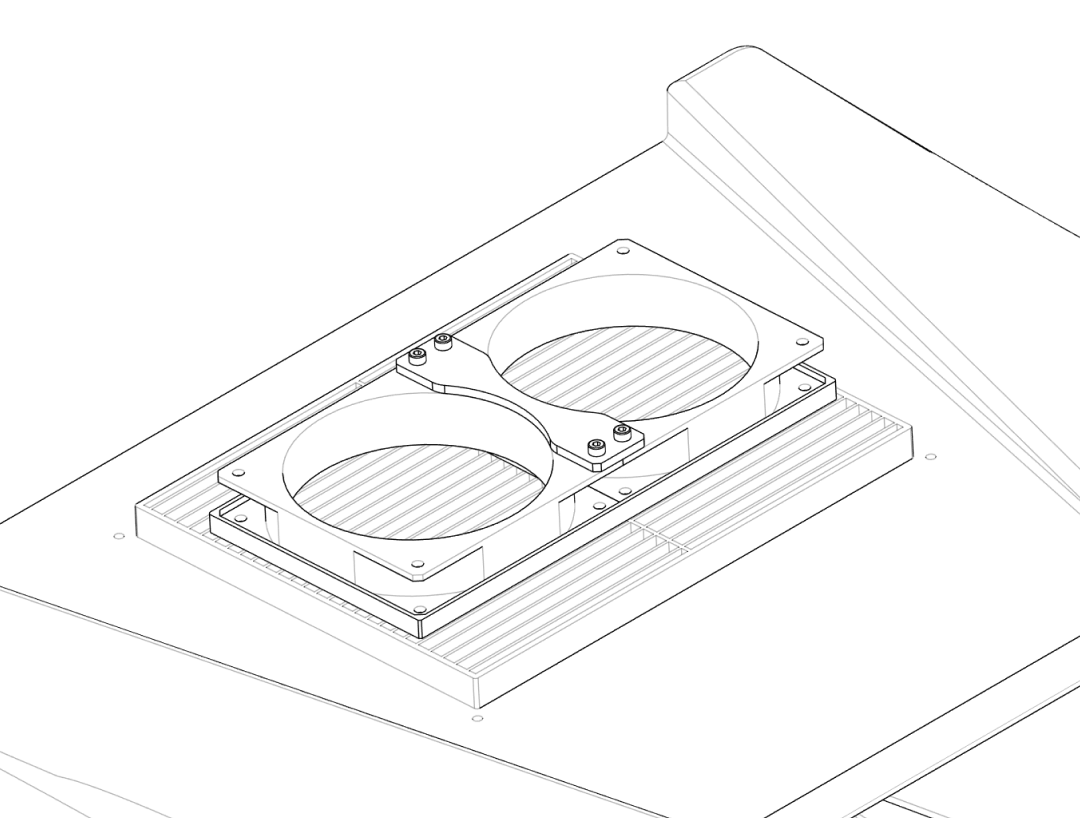
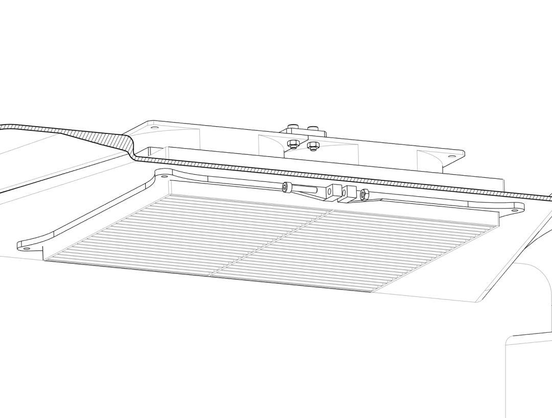
Step 3.2 – Clamp fan and filter together#
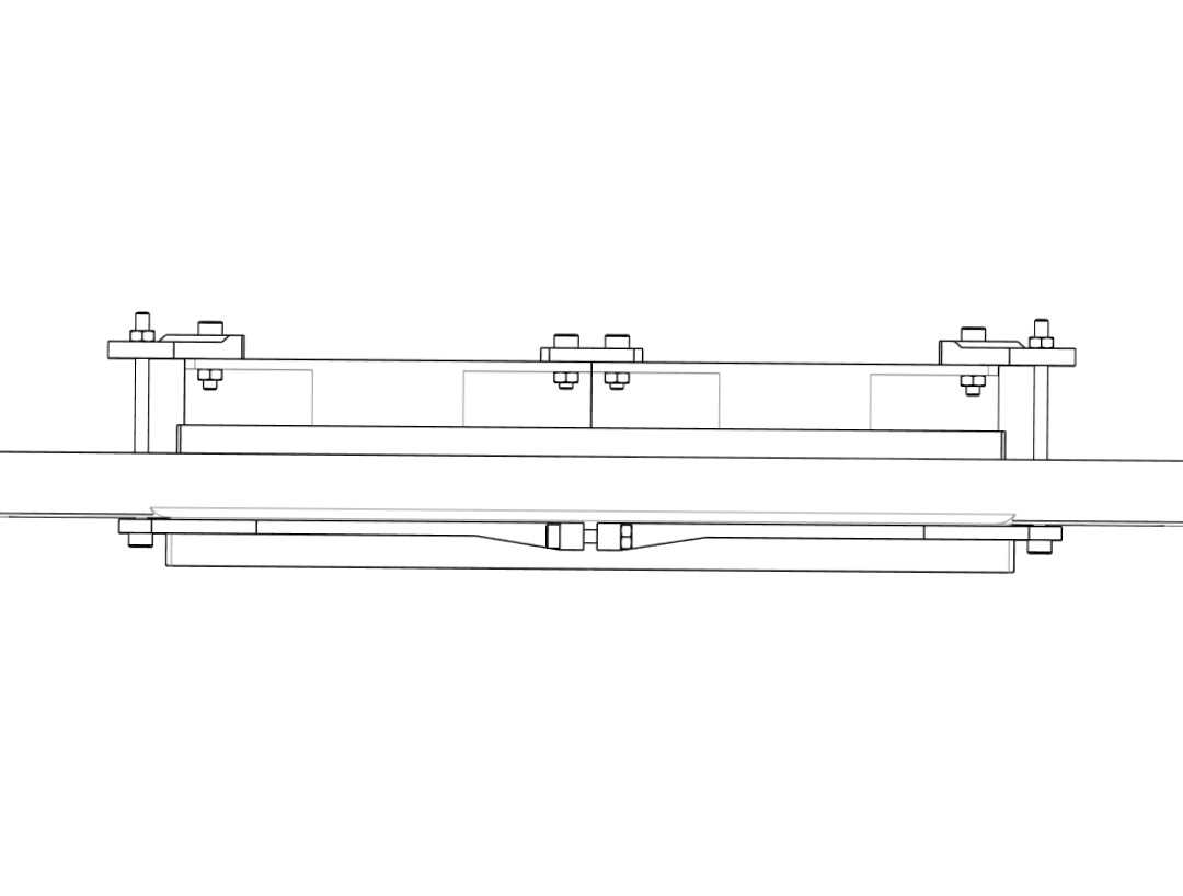
- Place the assembled fan module on the outside of the box, over the rectangular opening.
- Align the fan bracket holes with the drilled M4 holes and the
Filter_Holder‑Clamps inside the box. - Insert four long M4 screws (e.g. M4 × 65 mm) from the outside through: fan bracket → box lid → filter clamp.
- On the inside, place M4 nuts on each screw and tighten them evenly until the filter and fan are clamped firmly and the plastic deforms only slightly.
- Verify that the fan blades spin freely and that the filter frame is compressed all around for a good seal.
Do not overtighten
Excessive torque on the screws may crack the box wall or warp the filter frame. Tighten only until nothing moves when pushed gently.
4. Box inserts (cable and service ports)#
This section covers the smaller side ports: a cable feedthrough and a larger service port (65–72 mm insert).
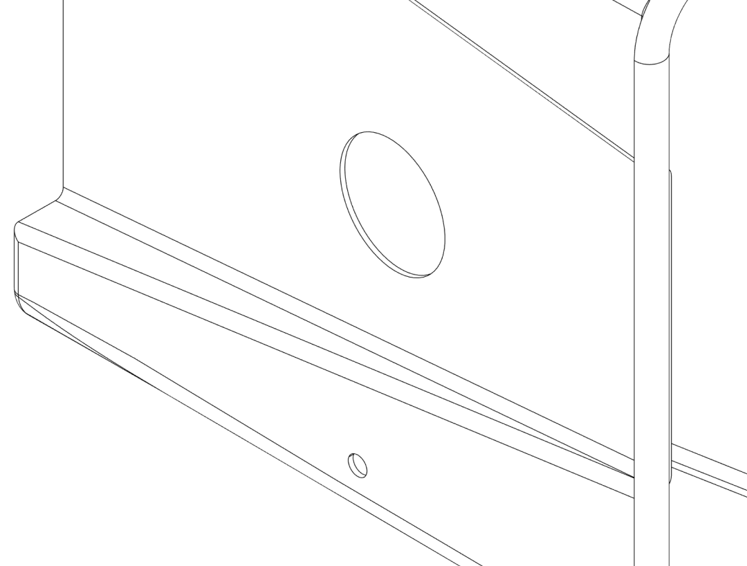
Step 4.1 – Cable insert#
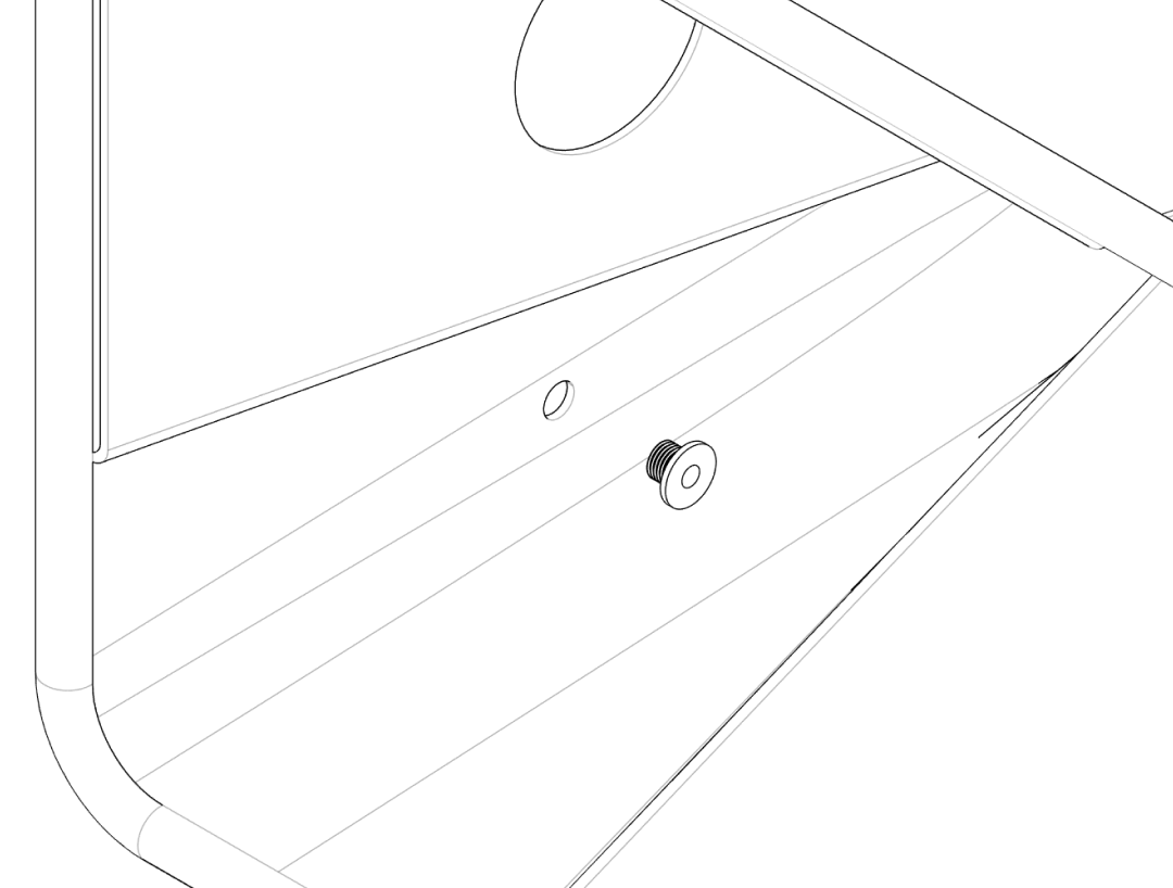
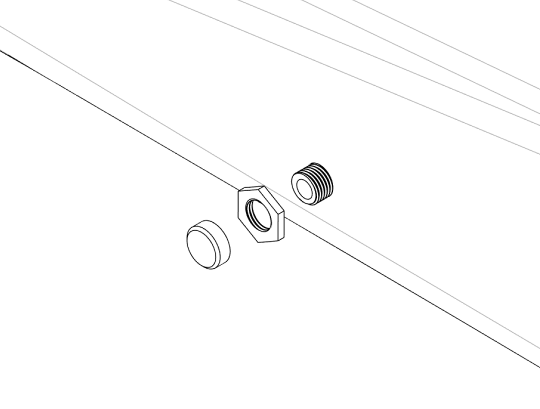
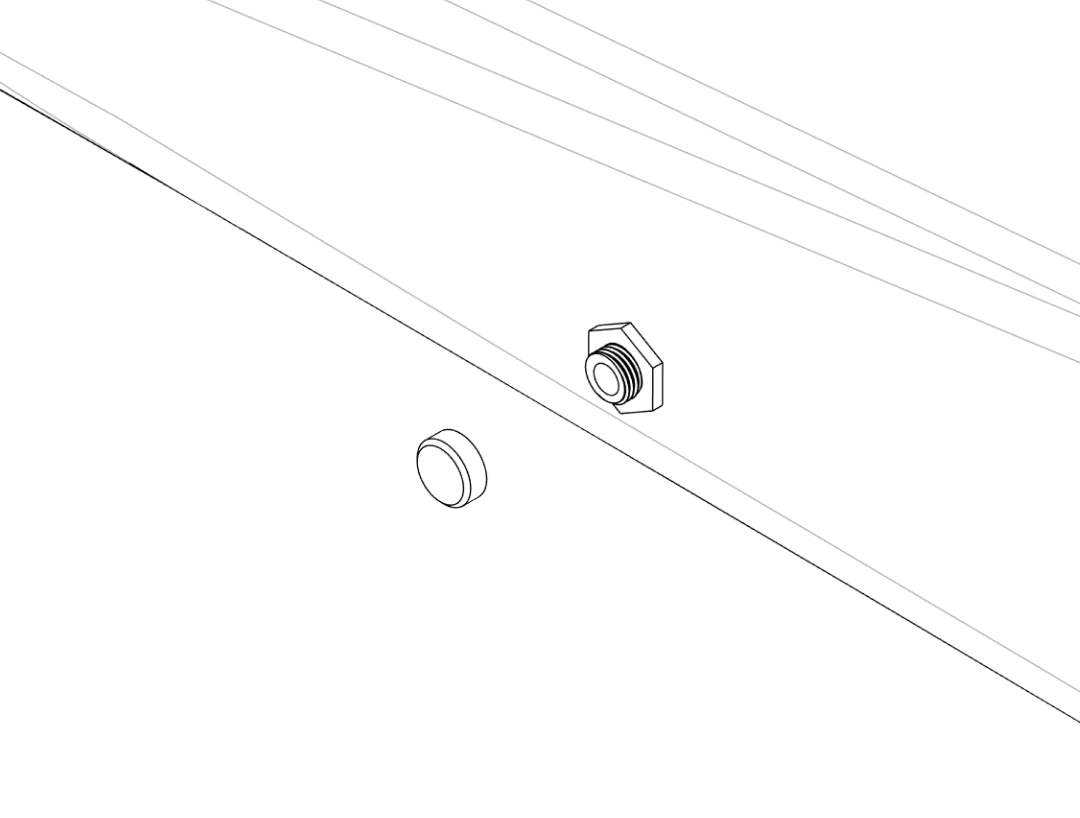
- From the inside of the box, insert the
Cable‑Insert_Innerthrough the 12 mm cable hole. - From the outside, thread the
Cable‑Insert_Nutonto the protruding part and hand‑tighten until the box wall is clamped firmly between the two parts. - When no cables are routed, close the port with the
Cable‑Insert_Cover. - To route a cable, remove the cover, feed the cable through, and reseal as well as possible with tape or a custom drilled cover.
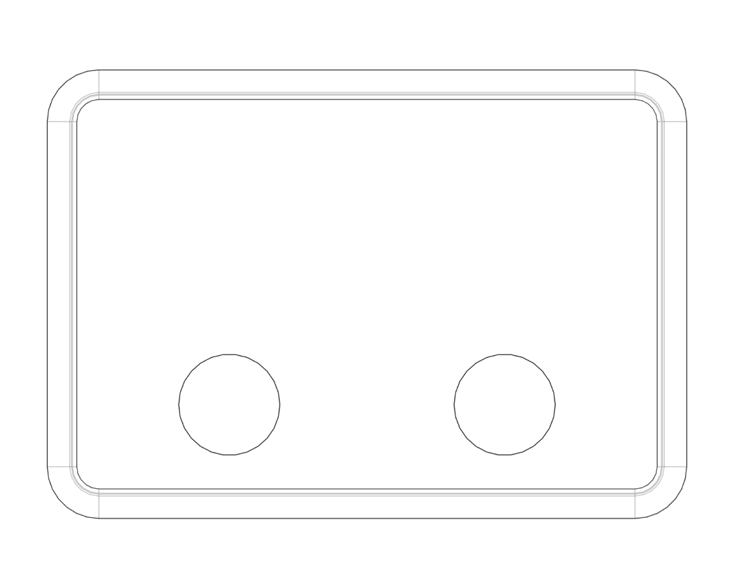
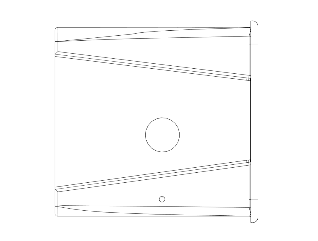
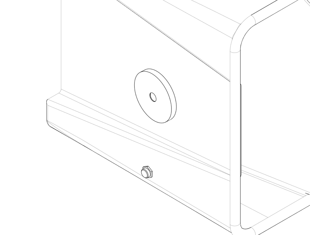
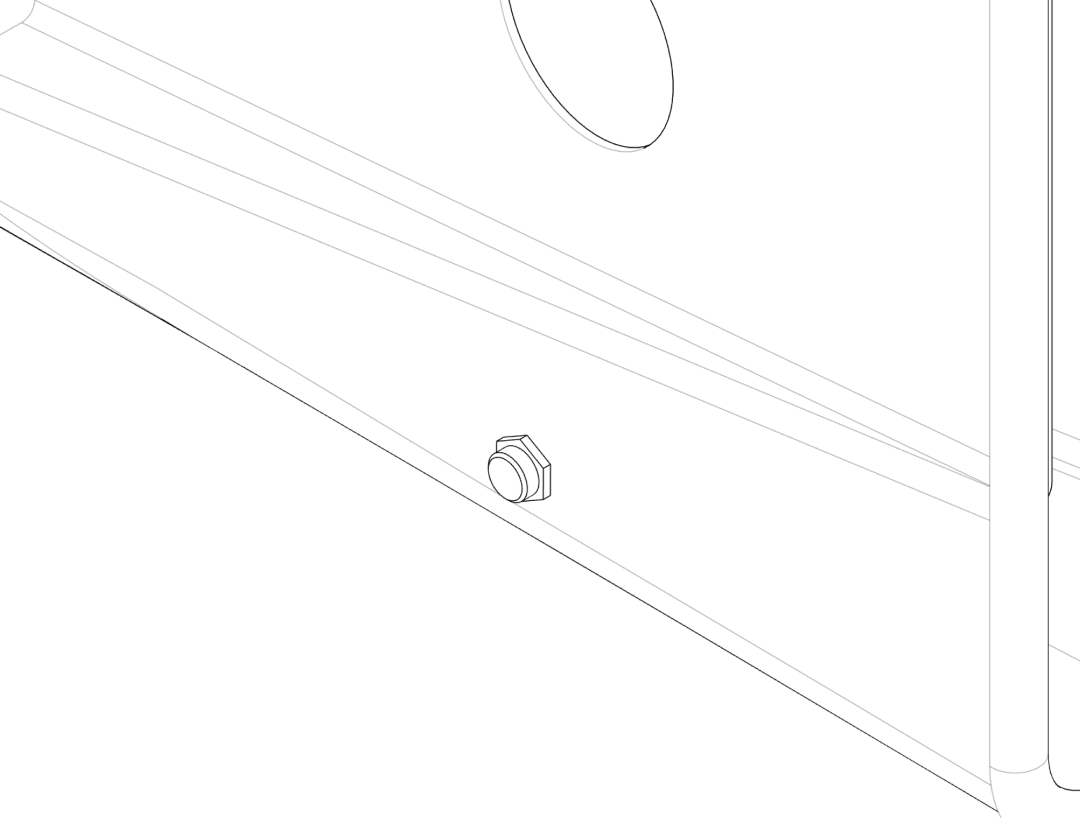
Step 4.2 – Large service insert (65–72 mm)#
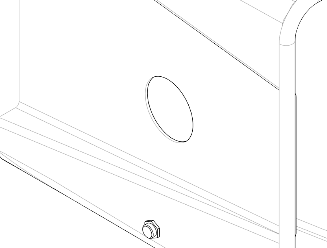
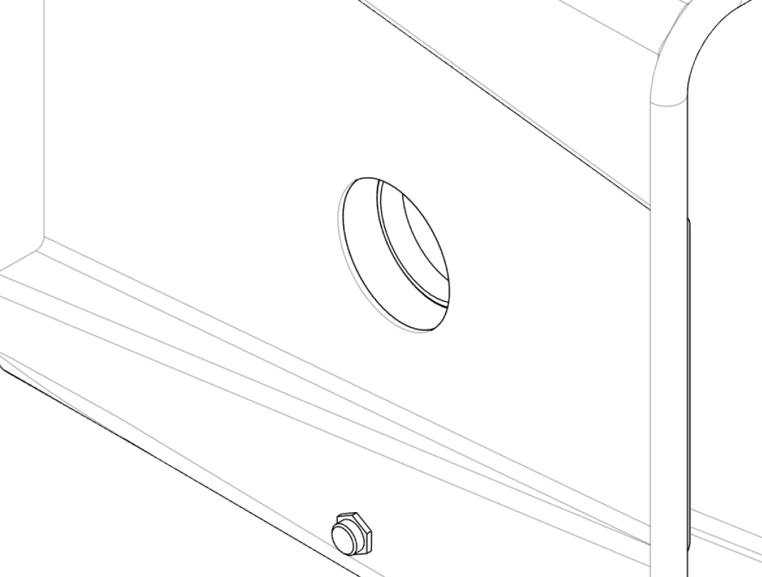
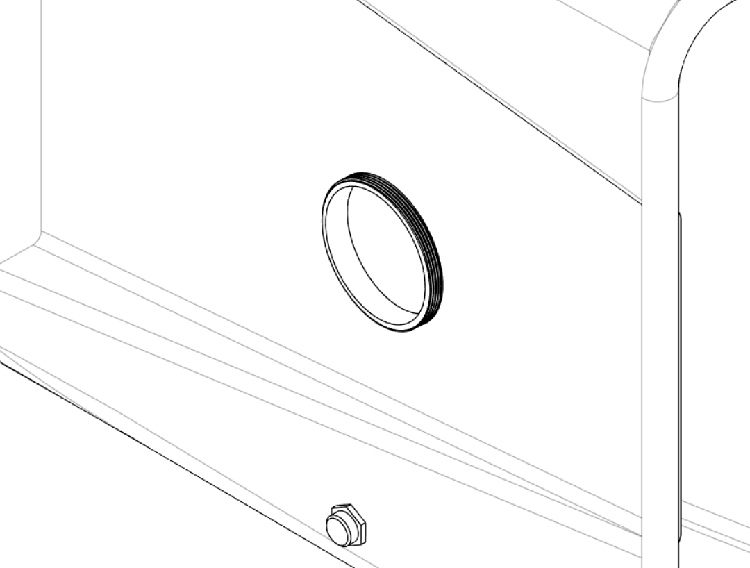
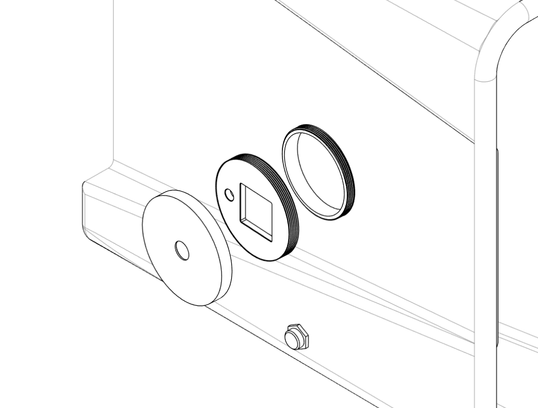
- From the inside of the box, place the
Large‑Insert_Innerinto the 72 mm side opening. - From the outside, align the appropriate outer cover (
Large‑Insert_Outer‑Cover‑OpenorLarge‑Insert_Outer‑Cover‑Closed) and fasten it to the inner part according to the design (screws or bayonet lock). - Use the closed cover when maximum sealing is required.
- Use the open cover variant to pass larger objects in or out of the box while keeping the opening controlled and easy to re‑seal.
5. Gloves#
Step 5.1 – Choosing gloves#
Select gloves that:
- Are long enough to reach all areas in the box.
- Have a cuff diameter compatible with the Glove‑Insert_Inner and Glove‑Insert_Outer‑Ring.
- Are made from a material resistant to any solvents or chemicals you expect to use (e.g. nitrile or thicker dishwashing gloves).
Test fit one glove first
Before assembling both ports, test the fit with one glove and adjust how far you roll the cuff to achieve a good seal and comfortable reach.
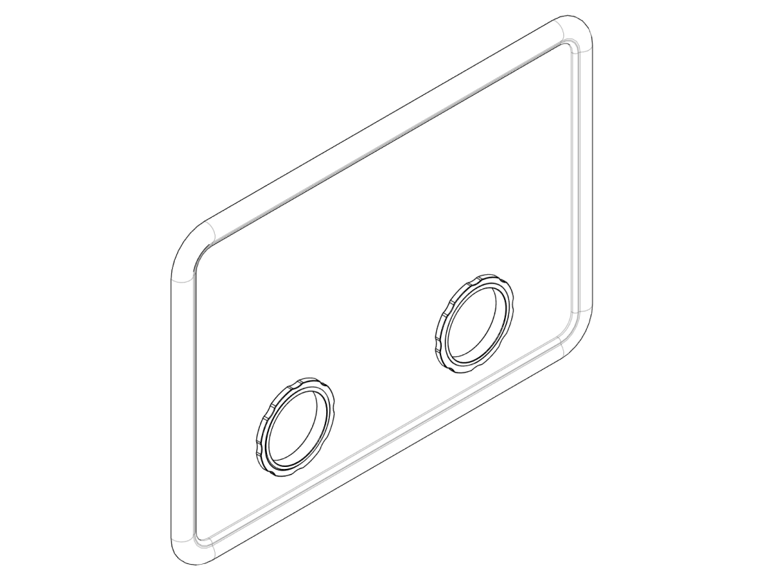
Step 5.2 – Mounting the glove screw‑on inserts#
- Turn the lid so the inside faces up. Insert the
Glove‑Insert_Innerinto one of the 96 mm circular openings from the inside. - Slide the glove cuff over the inner insert so that ~3–5 cm of the glove overlaps the flange.
- Place the
Glove‑Insert_Outer‑Ringover the glove from the outside of the lid and push it onto the inner insert, clamping the glove material in between. - Ensure the glove is clamped evenly all around and cannot be pulled out by gentle force.
- Repeat the procedure for the second glove port.
Do not overstretch the glove cuff
Overstretching can lead to tears. If the glove material feels too tight, choose a larger insert size or a different glove model.
6. Wiring and first test#
Step 6.1 – Connect fans to the power supply#
Mains safety
If you need to modify a mains‑powered supply, only do so if you are qualified to work with mains voltages. Otherwise use an off‑the‑shelf, enclosed 12 V supply and keep all mains wiring outside the glove box.
- Connect both 120 mm fans in parallel to the 12 V DC output of your power supply:
- All positive (red) wires together to +12 V.
- All negative (black) wires together to GND.
- If you want adjustable airflow, you can add a simple fan controller or a PWM speed control module between the supply and the fans.
- Route the fan power cable along the box by taping it or at least make sure it won't accidentally get into the fan blades.
Step 6.2 – Check overpressure and leaks#
- Close the lid and ensure all ports (large insert, cable insert, glove rings) are fully assembled.
- Turn on the fans. After a few seconds, the lid may bulge slightly as pressure builds.
- Hold a thin strip of tissue paper or incense stick near (not inside) suspected leak points around the lid and inserts: the strip should blow outwards, not be sucked in.
- If you detect inward leaks, check and re‑seat the inserts or consider adding sealing tape.
Your overpressure glove box is now ready to use for clean assembly of the Raman optical components.